Eureka AIR delivers breakthrough ideas for toughest innovation challenges, trusted by R&D personnel around the world.

Laser Shock Peening Apparatus for Surface of Workpiece, and Laser Shock Peening Method

a technology of laser shock peening and workpiece, which is applied in the direction of laser beam welding apparatus, welding apparatus, manufacturing tools, etc., can solve the problems of low energy utilization ratio, extremely high price of laser, and nearly 50% energy loss

Active Publication Date: 2016-08-18
NINGBO INST OF MATERIALS TECH & ENG CHINESE ACADEMY OF SCI
View PDF8 Cites 19 Cited by
  • Summary
  • Abstract
  • Description
  • Claims
  • Application Information

AI Technical Summary

Benefits of technology

The patent describes a device that uses laser technology to strengthen the surface of a workpiece. This device can make laser shock peening more efficient and reliable, leading to improved performance and reliability of the workpiece.

Problems solved by technology

That is, nearly 50% of energy is lost during the process of the existing laser shock peening, which means very low energy utilization ration.
However, such a laser has an extremely high price, and meanwhile, the laser system has lower reliability due to working under limiting condition.
However, the confinement layer utilizing the water film has the following problems that: (1) it is hard to stably control the thickness of the water film to about 0.5-1 mm in practical operation, for example, at present, the water film is typically applied from one side through a nozzle, however, the thickness of the water film is easy to vary with the shape and position of the workpiece, and the water film is easy to be damaged or sputter due to shock waves during the process, thereby influencing the uniformity of processing and the reliability of optical devices; and (2) compare with solid confinement, the water film has a deficient confinement rigidity, so that it has poor confinement effect on shock waves, and thus conditions, such as unstable confinement and the like, are easy to occur, which finally leads to attenuation of laser shock peening.
However, it has poor processing adaptability, which does not meet the requirement on local shock regions with relatively complex shapes.
Additionally, glass may be broken under the effect of plasmas and shock waves, and thus only conforms to single shock, and cannot be used repeatedly.
The flexible sticking film may forms a sticking film integrating energy-absorbing layer and constraining layer into one body and possessing a certain flexibility, however, its confinement stiffness cannot reach that of glass, and has disadvantages, such as potential quality hazard, for example, existence of bubbles, and complex and tedious manufacturing operation for flexible sticking film, which do not facilitate its promotion in the present field.

Method used


Image

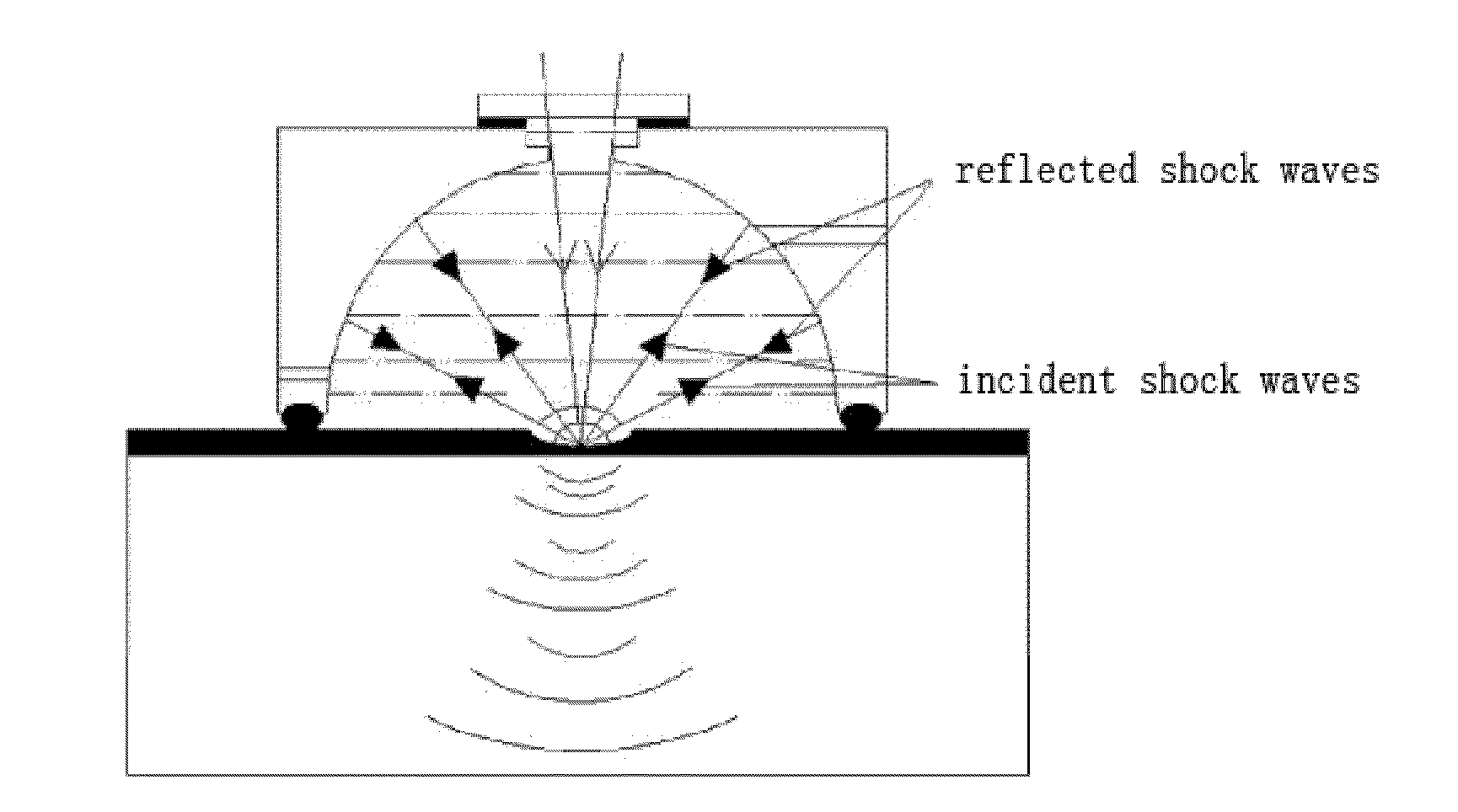
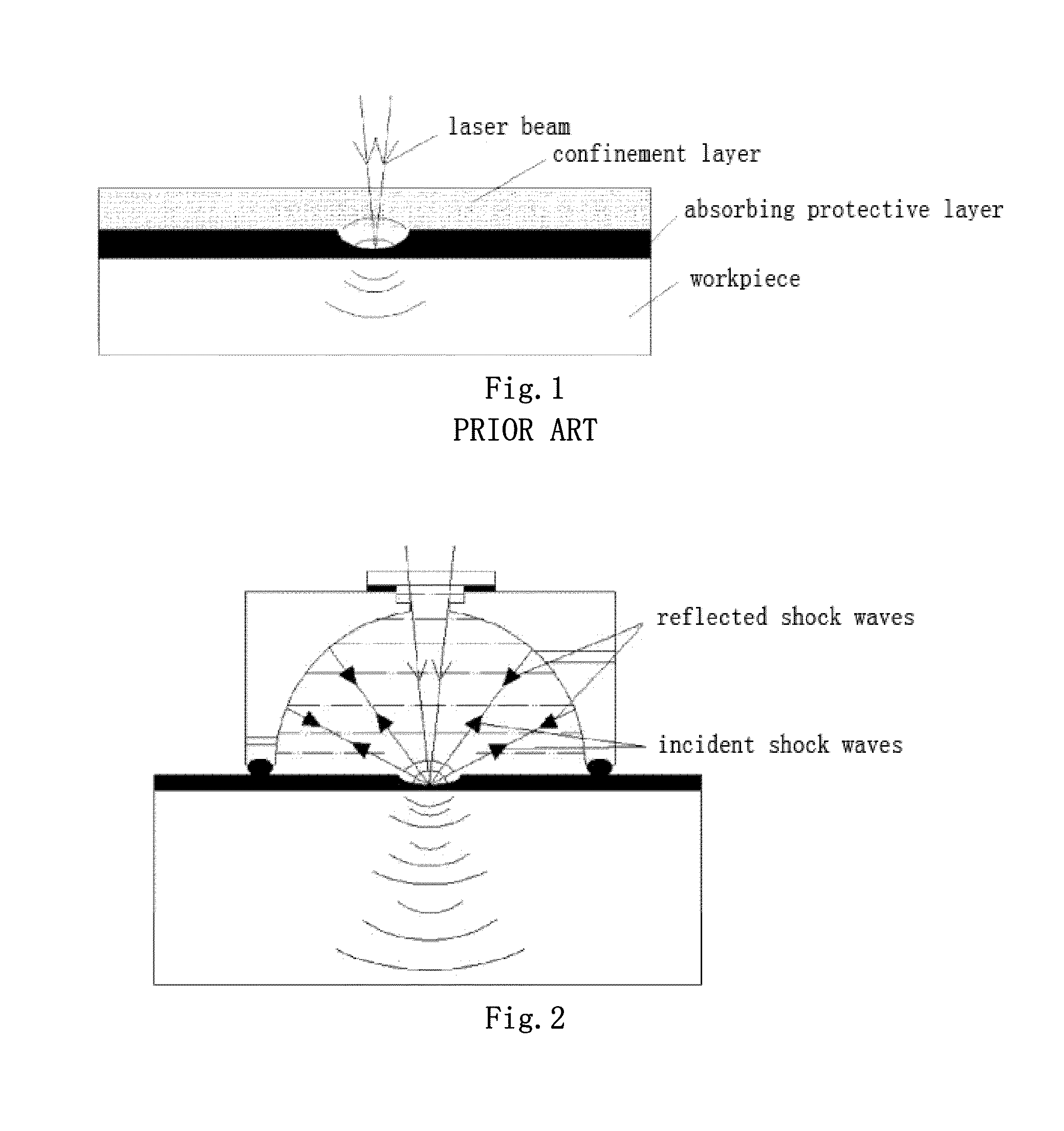
  • Laser Shock Peening Apparatus for Surface of Workpiece, and Laser Shock Peening Method
  • Laser Shock Peening Apparatus for Surface of Workpiece, and Laser Shock Peening Method
  • Laser Shock Peening Apparatus for Surface of Workpiece, and Laser Shock Peening Method

Examples


embodiment 1

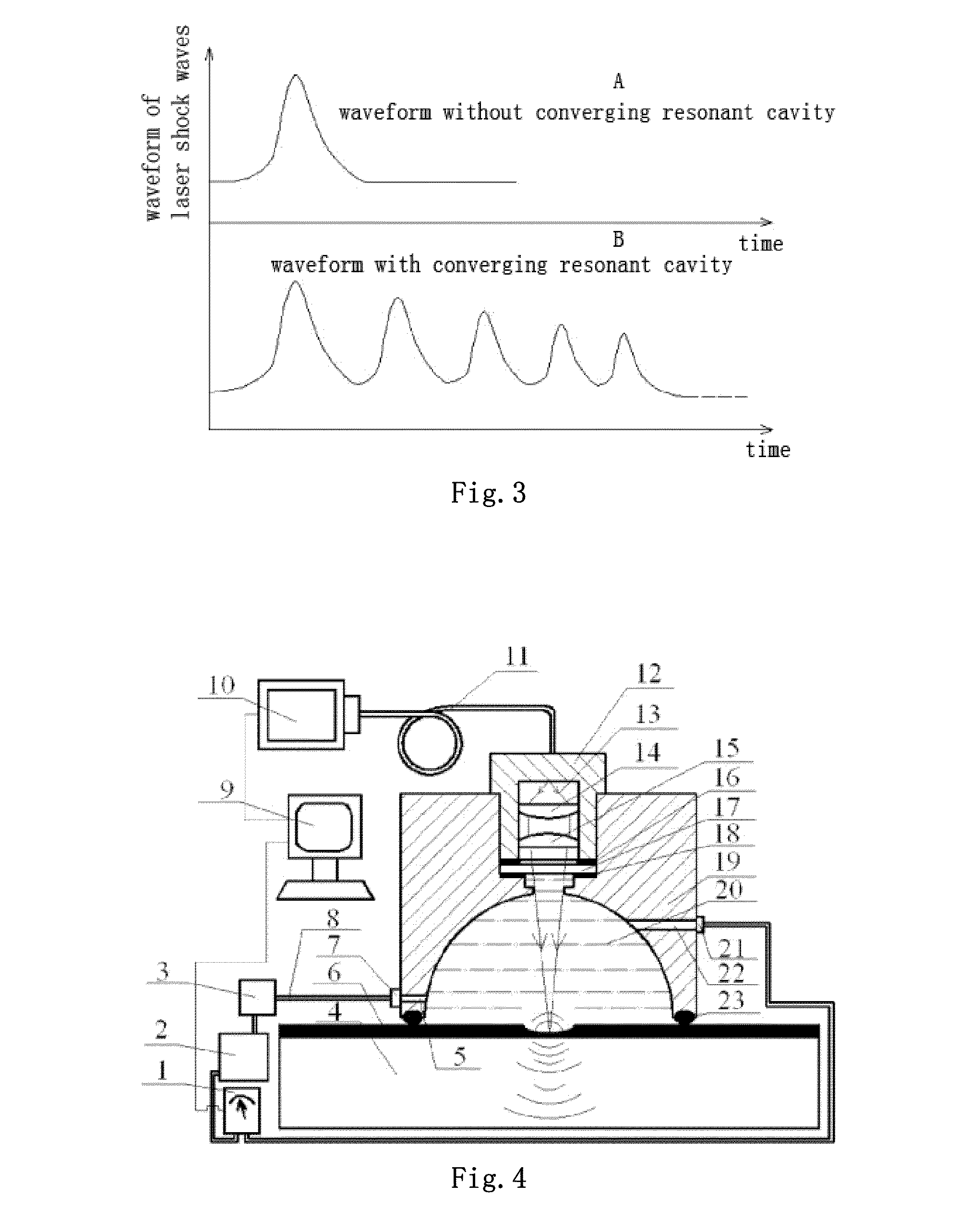
[0067]In the present embodiment, a laser shock peening apparatus, as shown in FIG. 4, comprises a laser generating unit 10 and a resonant cavity 19 with an open end, and the open end of the resonant cavity 19 hermetically contacts with the surface of an absorbing protective layer 6, thereby forming a “backoff” structure. The resonant cavity 19 is further provided with a laser inlet 13, a fluid inlet 22 and a fluid outlet 5.

[0068]The absorbing protective layer 6 is provided on the surface of the workpiece 4 to be processed, in the present embodiment, the workpiece 4 is a metal workpiece, and the absorbing protective layer 6 is a piece of aluminum foil. The confinement layer 20 is provided on the surface of the absorbing protective layer 6. The confinement layer 20 is located in the resonant cavity 19, and the confinement layer 20 is deionized water injected through the fluid inlet 22. The deionized water is pumped into the resonant cavity 19 through the pipes 8 and the fluid inlet 22...

embodiment 2

[0087]In the present embodiment, a laser shock peening apparatus, as shown in FIG. 12, comprises a laser generating unit and a resonant cavity with an open end, wherein, the open end of the resonant cavity and the surface of an absorbing protective layer are contact with each other in a non-hermetical contacting manner, thereby forming a “backoff” structure. The resonant cavity is further provided with a laser inlet, a fluid inlet and a fluid outlet.

[0088]The absorbing protective layer is provided on the surface of the workpiece to be processed, in the present embodiment, the workpiece is a metal workpiece, and the absorbing protective layer is a piece of aluminum foil. The confinement layer is provided on the surface of the absorbing protective layer. The confinement layer is located in the resonant cavity, and the confinement layer is gas, such as air, nitrogen gas and the like, injected through the fluid inlet. The gas is pumped into the resonant cavity through the fluid inlet by...


PUM

PropertyMeasurementUnit
thicknessaaaaaaaaaa
energyaaaaaaaaaa
flow rateaaaaaaaaaa

Abstract

A laser shock peening apparatus for the surface of a workpiece, said apparatus comprising a resonant cavity. When said apparatus is used to conduct laser shock peening, because of the presence of the resonant cavity, shock waves that would typically escape outward may instead be utilized, and composite shock waves may be formed as a result of the wave reflection and convergence effects of the resonant cavity. Said waves can then be used on the surface of a workpiece twice or multiple times, thereby greatly increasing energy utilization rates. In addition, a fluid-based confinement layer is limited to the inside of the resonant cavity and has a fixed shape, thereby effectively solving the problems of the poor stability of a fluid-based confinement layer and the difficulty with controlling the thickness of such a confinement layer.

Description

TECHNICAL FIELD OF THE INVENTION[0001]The present invention relates to the technical field of laser shock peening for the surface of a workpiece, and particularly, to a laser shock peening apparatus for the surface of a workpiece and a method for strengthening the surface of the workpiece by the laser shock peening apparatus.BACKGROUND OF THE INVENTION[0002]Laser shock peening technology is a technology for strengthening the surface of a workpiece through laser shock peening using ultra-high pressure shock waves generated by high power laser. At present, laser shock peening technology is widely used in various fields, such as aviation, shipbuilding, mechanical engineering fields, etc., especially, in anti-fatigue treatment for engine blades of aircraft.[0003]The existing laser shock peening apparatus for the surface of a workpiece comprises a laser generating unit, an absorbing protective layer on the surface of the workpiece, and a confinement layer on the absorbing protective laye...

Claims


Application Information

Patent Timeline
Patent Type & Authority Applications(United States)
IPC IPC(8): C21D10/00B23K26/0622B23K26/356
CPCC21D7/06B23K26/00B23K26/356B23K26/0622C21D10/005B23K26/127
Inventor ZHANG, WENWU
Owner NINGBO INST OF MATERIALS TECH & ENG CHINESE ACADEMY OF SCI
Why Eureka
Eureka Blog
Learn More