Air conditioner system for vehicle

a technology for air conditioners and vehicles, which is applied in the direction of compression machines with several condensers, light and heating apparatus, transportation and packaging, etc. it can solve the problems of deterioration of air-conditioning performance, excessive expansion of the cooling module package mounted at the front side of the vehicle, and increase the temperature of air induced into the air-cooled condenser, so as to improve installation and assembly. , the effect of reducing the noise of the blower fan

Active Publication Date: 2017-08-31
HANON SYST
View PDF54 Cites 11 Cited by
  • Summary
  • Abstract
  • Description
  • Claims
  • Application Information

AI Technical Summary

Benefits of technology

[0019]According to the present invention, because the air-cooled condenser mounted on the refrigerant circulation line between the water-cooled condenser and the expansion valve and the blower fan for blowing air to the air-cooled condenser are arranged on one side of the water-cooled condenser in a state of being disposed in a row in the air flow direction and are arranged within the width of the one side of the water-cooled condenser, the air conditioner system for a vehicle can enhance installability and assemblability inside the engine room by simplifying and reducing the package.
[0020]Moreover, the air conditioner system for the vehicle according to the present invention can reduce noise of the blower fan and secure adequate cooling performance because the blower fan is disposed between two air-cooled heat exchangers even when inflowing air is insufficient, such as in an idling condition.
[0021]Furthermore, because sufficiently liquefied refrigerant is induced into the receiver drier due to installation of the air-cooled condenser, the air conditioner system for the vehicle according to the present invention can secure the original function of the receiver drier and utilize the air-cooled condenser as a supercooling region to enhance air-conditioning performance.
[0022]Additionally, because the air-cooled condenser is mounted at the front side of the water-cooled condenser, the air conditioner system according to the present invention reuses the air passing through the air-cooled condenser to cool the water-cooled condenser, thereby enhancing cooling performance and improving fuel efficiency by reducing power consumption of the compressor.
[0023]In addition, because the air-cooled condenser is arranged at the front of the water-cooled condenser, the air conditioner system according to the present invention is easy to construct the package, provides the package in various designs, and enhances installability inside the engine room of the vehicle.
[0024]Moreover, because the air-cooled condenser is mounted not at the front side of the vehicle but on the cowl panel to supply the outdoor air of the cowl panel to the air-cooled condenser, thereby simplifying and reducing the package of the entire air conditioner system, reducing the refrigerant amount and manufacturing costs by making the refrigerant circulation line short, and enhancing air-conditioning performance by effectively supplying air to the air-cooled condenser.

Problems solved by technology

However, if the air-cooled condenser is mounted at the front side of the vehicle, a cooling module package mounted at the front side of the vehicle becomes excessively bigger.
Moreover, when the vehicle idles, because air of high-temperature in an engine room flows backward toward the front side of the vehicle and is induced into the air-cooled condenser, temperature of the air induced into the air-cooled condenser gets higher, and it causes deterioration in air-conditioning performance.
Additionally, due to the limit of the outdoor temperature which cools the coolant of the water-cooled radiator 50, temperature of the coolant of the water-cooled radiator 50 is high and the water-cooled condenser 20 does not provide sufficient condensation in the condensing region, and hence, gas-liquid separation is not achieved smoothly in the receiver drier 30 due to high quality of the refrigerant induced into the receiver drier 30.
In addition, because the water-cooled condenser 20, the receiver drier 30 and the internal heat exchanger 25 are arranged disorderedly, the package becomes excessively bigger and it is not easy to mount them inside the engine room of the vehicle.

Method used


Image

  • Air conditioner system for vehicle
  • Air conditioner system for vehicle
  • Air conditioner system for vehicle

Examples


Embodiment Construction

[0049]Reference will be now made in detail to the preferred embodiment of the present invention with reference to the attached drawings.

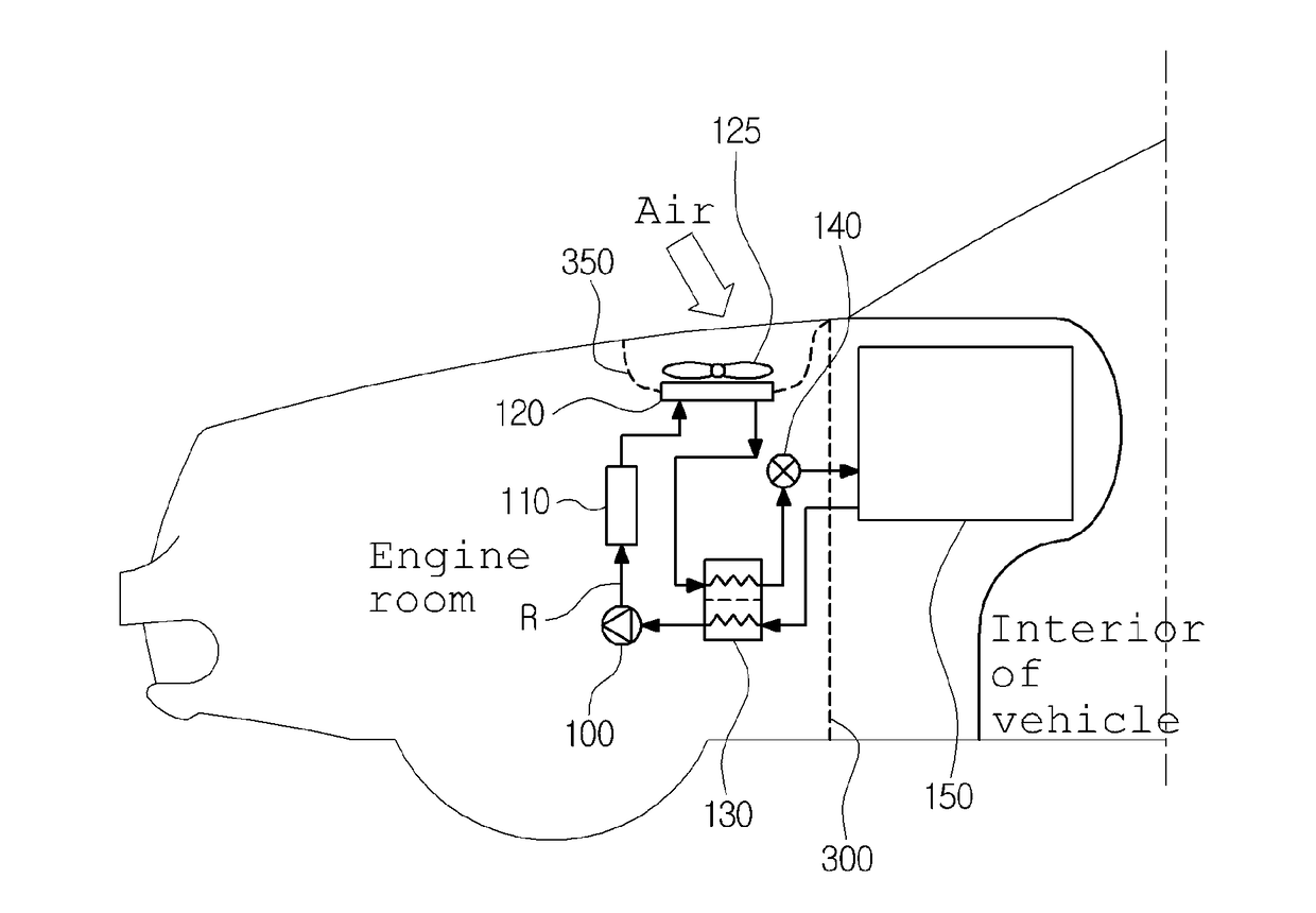
[0050]As shown in the drawings, an air-conditioner system for a vehicle according to a first preferred embodiment of the present invention is configured of a compressor 100, a water-cooled condenser 110, an expansion valve 140 and an evaporator 150 which are connected to a refrigerant pipe P in order, and includes an air-cooled condenser 120, a receiver drier 160 and an internal heat exchanger 130 mounted between the water-cooled condenser 110 and the expansion valve 140 in the above-mentioned system.

[0051]First, the compressor 100 inhales and compresses gas-phase refrigerant of low-temperature and low-pressure discharged from the evaporator 150 and discharges the gas-phase refrigerant into a gaseous state of high-temperature and high-pressure while receiving a driving power from a driving power supply source, such as, an engine or a motor.

[0052]The...


PUM


Abstract

The present invention relates to an air conditioner system, in which an air-cooled condenser mounted on a refrigerant circulation line between a water-cooled condenser and an expansion valve and a blower fan for blowing air to the air-cooled condenser are arranged at one side of the water-cooled condenser in a state of being disposed in a row in the air flow direction and are arranged within the width of the one side of the water-cooled condenser, thereby enabling the enhancement of installability and assemblability inside an engine room by simplifying and reducing the package, reducing noise of the blower fan and securing adequate cooling performance because of the blower fan disposed between two air-cooled heat exchangers even when inflowing air is insufficient, such as in an idling condition.

Description

TECHNICAL FIELD[0001]The present invention relates to an air conditioner system for a vehicle, and more particularly, to an air conditioner system for a vehicle, in which an air-cooled condenser mounted on a refrigerant circulation line between a water-cooled condenser and an expansion valve and a blower fan for blowing air to the air-cooled condenser are arranged on one side of the water-cooled condenser in a state of being disposed in a row in the air flow direction and are arranged within the width of the one side of the water-cooled condenser.BACKGROUND ART[0002]In general, as shown in FIG. 1, an air conditioner system for a vehicle has a refrigeration cycle that includes: a compressor 1 for compressing and discharging refrigerant; a condenser 2 for condensing the refrigerant of high pressure discharged from the compressor 1; an expansion valve 3 for throttling the refrigerant condensed and liquefied in the condenser 2; and an evaporator 4 for exchanging heat between the liquefi...

Claims


Application Information

Patent Timeline
Patent Type & Authority Applications(United States)
IPC IPC(8): B60H1/32
CPCB60H1/3229B60H2001/3288B60H2001/3291B60H1/3227F25B1/10F25B6/04F25B2339/047F25B2400/072B60H1/32281
Inventor LEE, HAE JUNAHN, YONG NAMLEE, SANG MINCHOI, JUN YOUNG
Owner HANON SYST
Why Eureka
Try Eureka