No-contact alignment apparatus and no-contact alignment method

a technology of no-contact alignment and alignment method, which is applied in the field of no-contact alignment apparatus and no-contact alignment method, can solve the problems of electrostatic charge build-up, unpolluted clean room environment, and the destruction of transistors located on glass substrates

Active Publication Date: 2010-12-07
INNOLUX CORP
View PDF8 Cites 2 Cited by
  • Summary
  • Abstract
  • Description
  • Claims
  • Application Information

AI Technical Summary

Benefits of technology

This method effectively creates an alignment surface for liquid crystal molecules without introducing debris or electrostatic charges, ensuring the integrity of transistors and enabling cleaner manufacturing processes.

Problems solved by technology

This is because the rubbing process introduces debris from the cloth into an otherwise unpolluted clean room environment.
The rubbing process can also lead to electrostatic charge build up, which can destroy transistors located on the glass substrate below the polyimide surface.

Method used


Image

  • No-contact alignment apparatus and no-contact alignment method
  • No-contact alignment apparatus and no-contact alignment method
  • No-contact alignment apparatus and no-contact alignment method

Examples


first embodiment

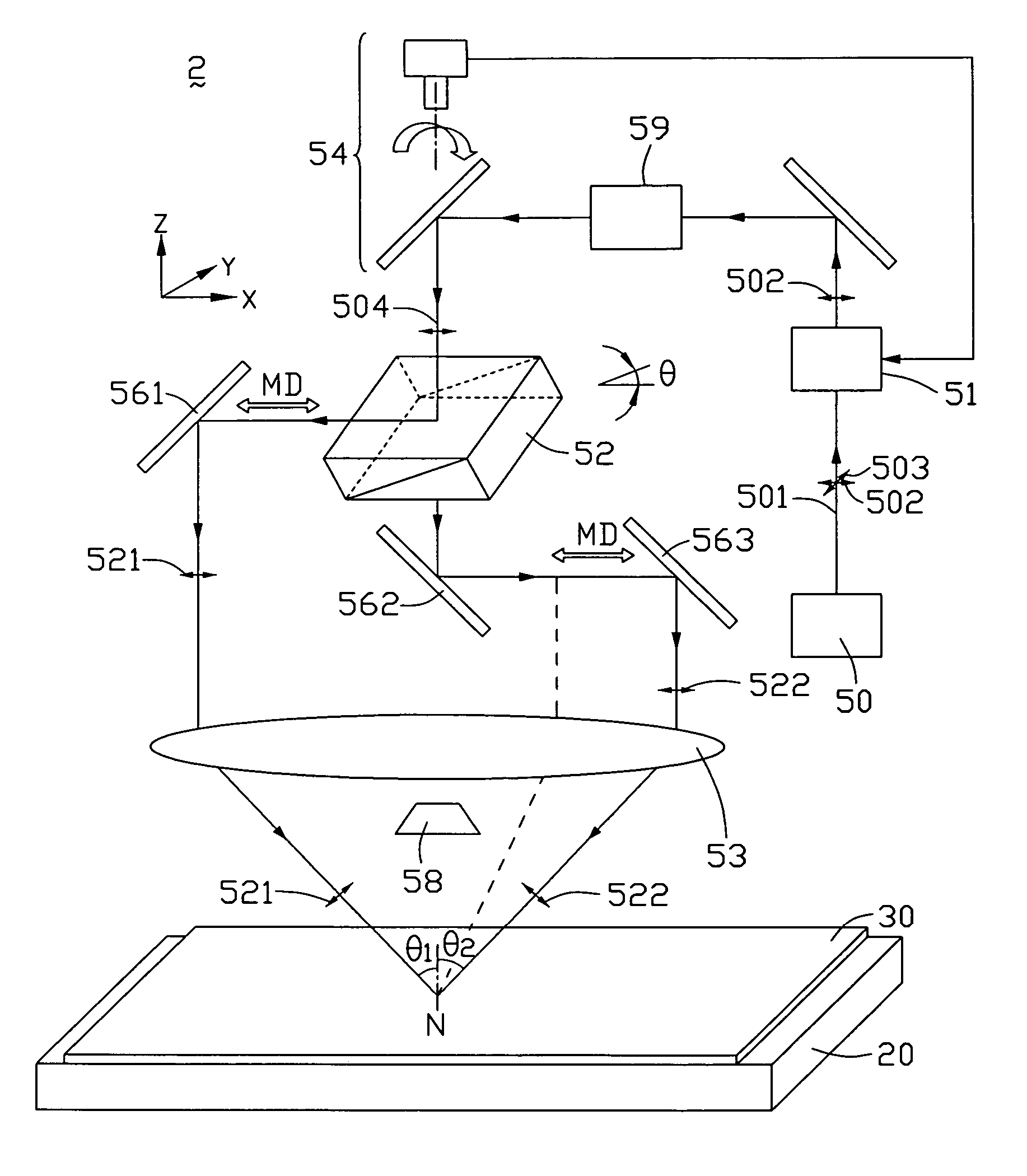
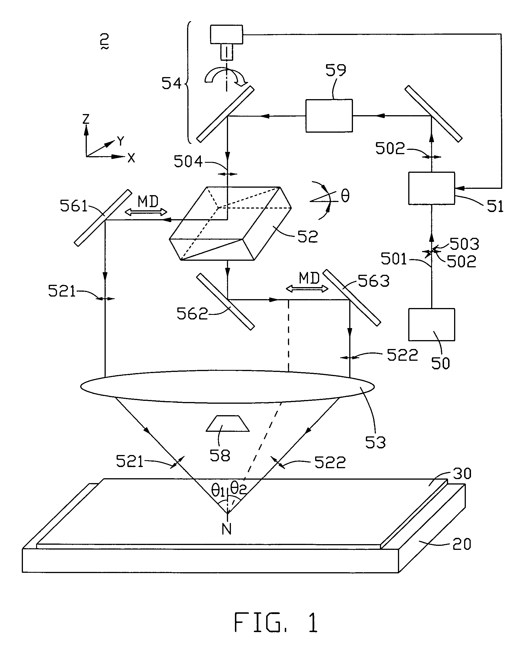
[0016]Referring to FIG. 1, an alignment apparatus 2 according to the present invention is shown. The alignment apparatus 2 includes a light source 50, a polarized light generator 51, a polarized light separator 52, a light controller 54, a light reflector (not labeled), a convergent lens 53, a vent-pipe 58, and a light intensity controller 59. The light source 50 is a high voltage light source, and emits ultraviolet light. The polarized light generator 51 generates a linear polarized light beam, and the polarized light separator 52 separates the polarized light beam into two polarized light beams by way of internal reflection and transmission of the polarized light beam. The light reflector includes a first reflecting mirror 561, a second reflecting mirror 562, and a third reflecting mirror 563. The light reflector changes a direction of a reflection polarized light beam passing therethrough and a direction of a transmission polarized light beam passing therethrough, such that the r...

second embodiment

[0033]Referring to FIG. 7, an alignment apparatus 3 according to the present invention is shown. The alignment apparatus 3 includes a light source 70, a polarized light generator 71, a polarized light separator 72, a light controller 74, a light reflector (not labeled), a vent-pipe 78, and a light intensity controller 79. The polarized light separator 72 may be a holographic diffractive optical element. The light reflector includes a first reflecting mirror 761, a second reflecting mirror 762, and a third reflecting mirror 763. Angles of the first and third reflecting mirrors 761, 763 relative to the horizontal plane are adjusted, so that a reflection polarized light beam and a diffraction light beam converge onto a photosensitive polymer layer 41 formed on a substrate 40.

[0034]Unlike with conventional alignment apparatuses, because the alignment apparatuses 2, 3 are no-rubbing, no-contact alignment apparatuses, debris and electrostatic charge are avoided or even eliminated.

[0035]An...


PUM

PropertyMeasurementUnit
wavelengthaaaaaaaaaa

Abstract

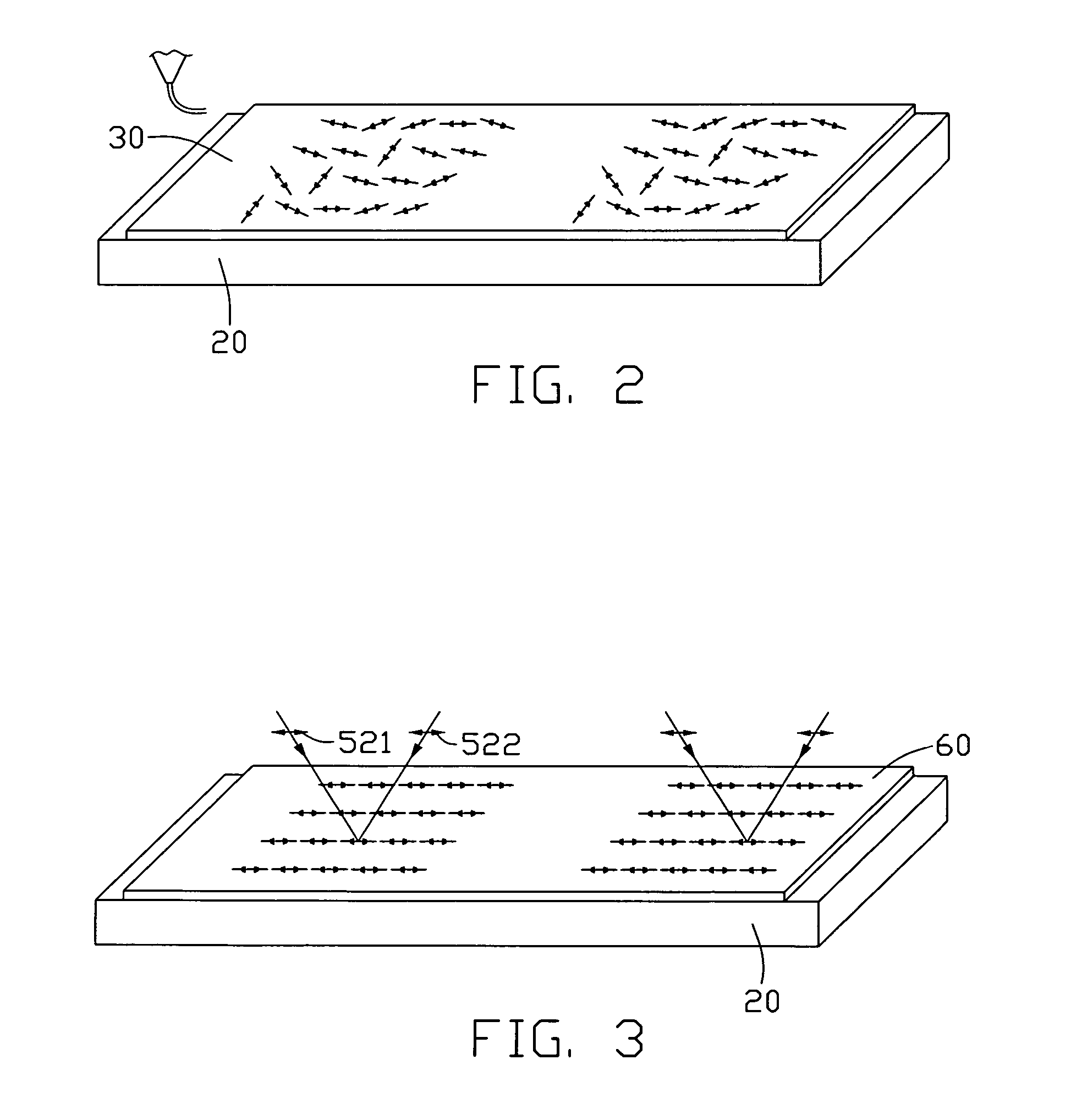
An exemplary alignment apparatus (2) includes a light source (50) for emitting light (501), a polarized light generator (51) for receiving the light and generating polarized light (504), a polarized light separator (52) for receiving the polarized light and separating the polarized light into a reflection polarized light beam (521) and a transmission polarized light beam (522) having capability to interfere with each other, a light reflector for changing transmission directions of the reflection and transmission polarized light beams to make the reflection and transmission polarized light beams parallel to each other, and a convergent lens (53) for making the reflection and transmission polarized light beams converge and interferingly irradiate a photosensitive polymer layer (30) to obtain an alignment layer (60). Unlike with conventional alignment apparatuses, because the alignment apparatus is no-rubbing, no-contact alignment apparatuses, debris and electrostatic charge are avoided or even eliminated.

Description

CROSS-REFERENCE TO RELATED APPLICATION[0001]This application is related to, and claims the benefit of, a foreign priority application filed in Taiwan as Serial No. 094137849 on Oct. 28, 2005. The related application is incorporated herein by reference.FIELD OF THE INVENTION[0002]The present invention relates to alignment apparatuses such as those used to make alignment layers of liquid crystal displays, and particularly to a no-contact alignment apparatus and a no-contact alignment method.GENERAL BACKGROUND[0003]A typical liquid crystal display (LCD) is capable of displaying a clear and sharp image through millions of pixels that make up the complete image. The liquid crystal display has thus been applied to various electronic equipment in which messages or pictures need to be displayed, such as mobile phones and notebook computers.[0004]In the manufacture of a typical LCD, an essential requirement is the alignment of liquid crystal molecules on a surface of an alignment layer (here...

Claims


Application Information

Patent Timeline
Patent Type & AuthorityPatents(United States)
IPC IPC(8): G02F1/1337G02F1/1335
CPCG02B27/0043G02B27/283G02F1/133788
InventorTSAI, MING-HUNG
OwnerINNOLUX CORP