
Catheter infusion port

a catheter and infusion port technology, applied in the direction of medical devices, other medical devices, etc., can solve the problems of wear and damage of the moving parts of the catheter, and achieve the effect of removing the avenue of blood clotting and unwanted growths

Active Publication Date: 2010-12-14
TWINCATH +1
View PDF31 Cites 9 Cited by
  • Summary
  • Abstract
  • Description
  • Claims
  • Application Information

AI Technical Summary

Benefits of technology

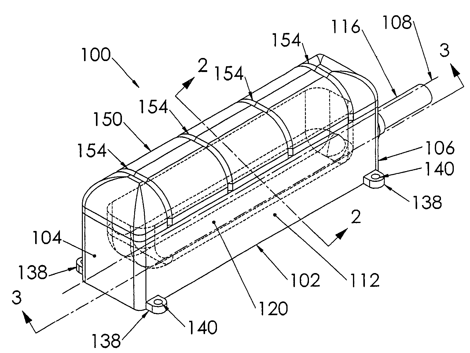
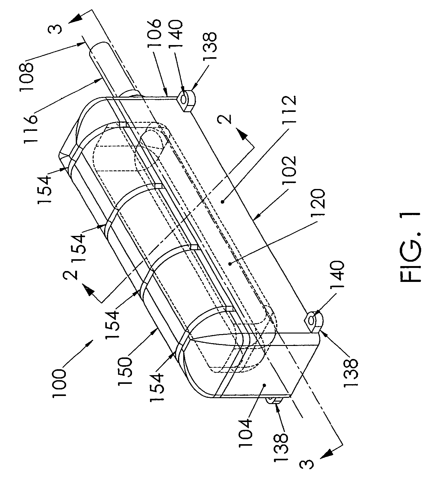
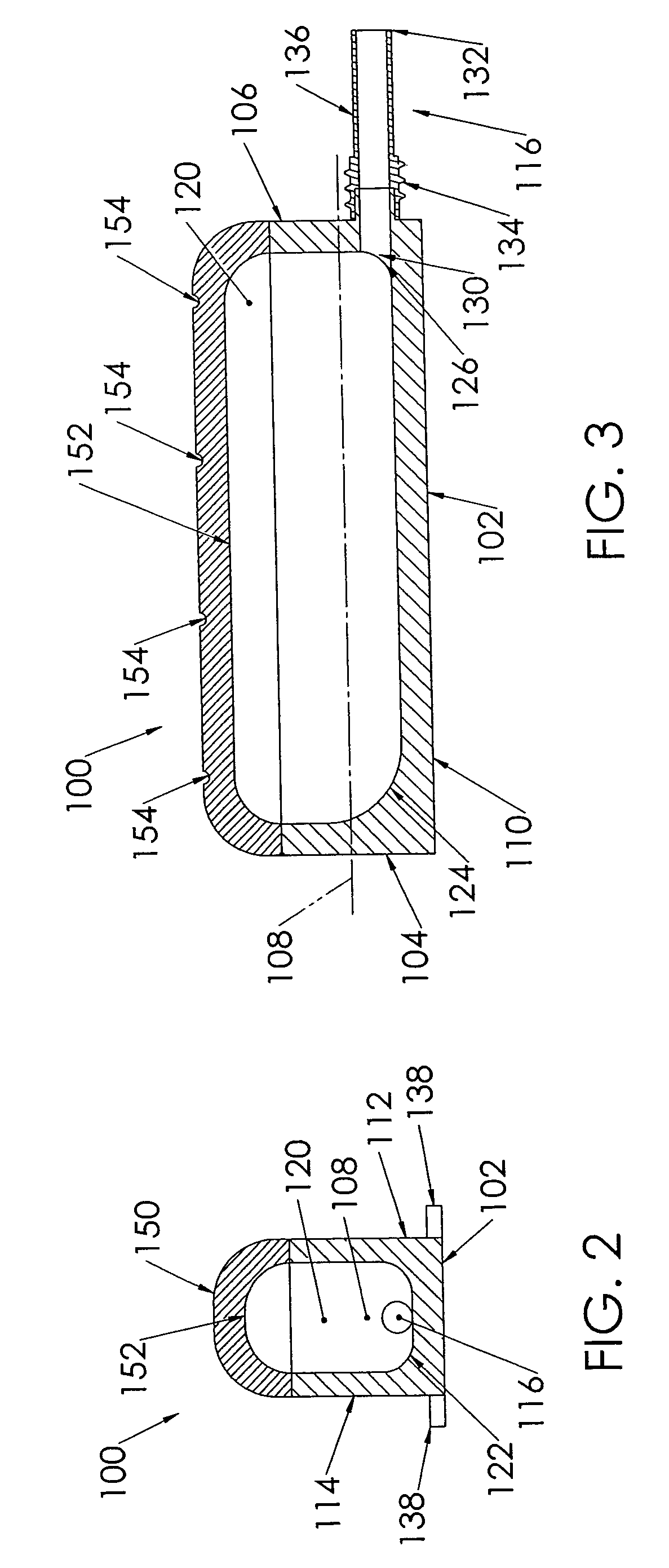
[0006]The present invention is a port for a catheter assembly, having a generally elongated body having a discharge port that extends through a distal wall, and a channel extending along the longitudinal axis to the proximal wall. The channel is U-shaped with a rounded portion disposed adjacent the bottom of the body and further having rounded corners adjacent the proximal and distal walls of the body. A cover for the body provides for insertion therethrough of a syringe needle for infusion and that seals upon needle withdrawal; the cover includes an inside surface that is convex upwardly and is rounded at its sides and ends to be generally smoothed into the sidewalls of the channel and the proximal and distal end walls of the body. Thus, the port is devoid of any sharp edges or corners, therefore eliminating an avenue of blood clotting and unwanted growths.

Problems solved by technology

Additionally, for the port designs that include valves, the moving parts associated with the valves may malfunction or wear over time, necessitating the removal of the port.

Method used


Image

  • Catheter infusion port
  • Catheter infusion port
  • Catheter infusion port

Examples


Embodiment Construction

[0012]In the drawings, like numerals indicate like elements throughout. As used herein, the terms “distal” and “proximal” are defined to mean directions closer to and away from, respectively, a catheter connection port of the present invention. The terminology includes the words specifically mentioned, derivatives thereof and words of similar import. The embodiments illustrated below are not intended to be exhaustive or to limit the invention to the precise form disclosed. These embodiments are chosen and described to best explain the principle of the invention and its application and practical use and to enable others skilled in the art to best utilize the invention.

[0013]A catheter port 100 according to a preferred embodiment of the present invention is shown in FIG. 1. The port 100 is used to provide a connection to a catheter that has previously been subcutaneously implanted into a patient, such as to administer medicaments or other fluids, or to withdraw fluids, such as blood, ...


PUM


Abstract

A port (100) for a catheter assembly (200), including a body (102) and a cover (150) and having a distal discharge port (116) for connection to an implanted catheter assembly. Within the body is a longitudinal U-shaped channel (120) extending to a proximal body wall (104) from the distal body wall (106) along a longitudinal axis parallel to the axis of the discharge port (116). The channel has a rounded bottom (122) and is also rounded at the channel ends (126,124) at the distal and proximal body walls. The cover (150) provides for penetration by a syringe needle and seals upon needle withdrawal, with the cover having an inside surface (152) concave and rounded between the distal and proximal ends and also longitudinally, being generally smoothed into the channel sides and ends. The port has no inner sharp edges or corners and eliminates blood clotting and unwanted growth sites.

Description

CROSS-REFERENCE TO RELATED APPLICATION[0001]This application claims priority from U.S. Provisional Patent Application Ser. No. 60 / 645,678 filed Jan. 21, 2005.FIELD OF THE INVENTION[0002]The present invention relates to a port for injecting a fluid into or for withdrawing a fluid from a catheter.BACKGROUND OF THE INVENTION[0003]Infusion ports for the infusion and / or withdrawal of fluids from a patient are well-known. These ports are typically used for drug infusion or small amounts of blood withdrawal, where large flows of fluid are not required. However, larger ports are used for activities such as hemodialysis or plasmapheresis. Typically, these ports incorporate mechanical valves which open during use, such as when a needle is inserted into the port, and which close in between use, such as when the needle is removed from the port.[0004]Such ports may be implanted subcutaneously and remain within the patient for prolonged periods of time. The ports provide an access site for multip...

Claims


Application Information

Patent Timeline
Patent Type & Authority Patents(United States)
IPC IPC(8): A61M37/00
CPCA61M39/0208A61M39/04
Inventor SCHON, DONALD ASCHWEIKERT, TIMOTHY M
Owner TWINCATH
Learn More