Thermal and acoustic valley shield for engine assembly

a technology of thermal valley shield and engine block, which is applied in the direction of machines/engines, mechanical equipment, light and heating equipment, etc., can solve the problems of reduced oxygen concentration and dilution effect, and achieve the effects of improving thermal resiliency and protective capacity, improving vibration attenuation, and improving damping performan

Inactive Publication Date: 2011-03-08
GM GLOBAL TECH OPERATIONS LLC
View PDF2 Cites 0 Cited by
  • Summary
  • Abstract
  • Description
  • Claims
  • Application Information

AI Technical Summary

Benefits of technology

[0007]The valley shields of the present invention are operable to act as a noise, fluid, and heat barrier between an internal combustion engine assembly and engine components positioned on an opposing side of the valley shield. The valley shields of the present design offer, among other things, improved acoustic damping performance, increased thermal resiliency and protective capacity, and improved vibration attenuation. In addition, the present design also offers enhanced fluid drainage characteristics with minimal fluid absorption, while allowing for more efficient packaging and ease of installation of the valley shield during engine assembly.

Problems solved by technology

First, there is a dilution effect caused by the reduction in the concentration of oxygen in intake air.
Second, there is a thermal effect caused by increasing the specific heat capacity of each charge.
Third, there is a chemical effect which results from the dissociation of CO2 and water vapor during combustion.

Method used


Image

  • Thermal and acoustic valley shield for engine assembly
  • Thermal and acoustic valley shield for engine assembly
  • Thermal and acoustic valley shield for engine assembly

Examples


Embodiment Construction

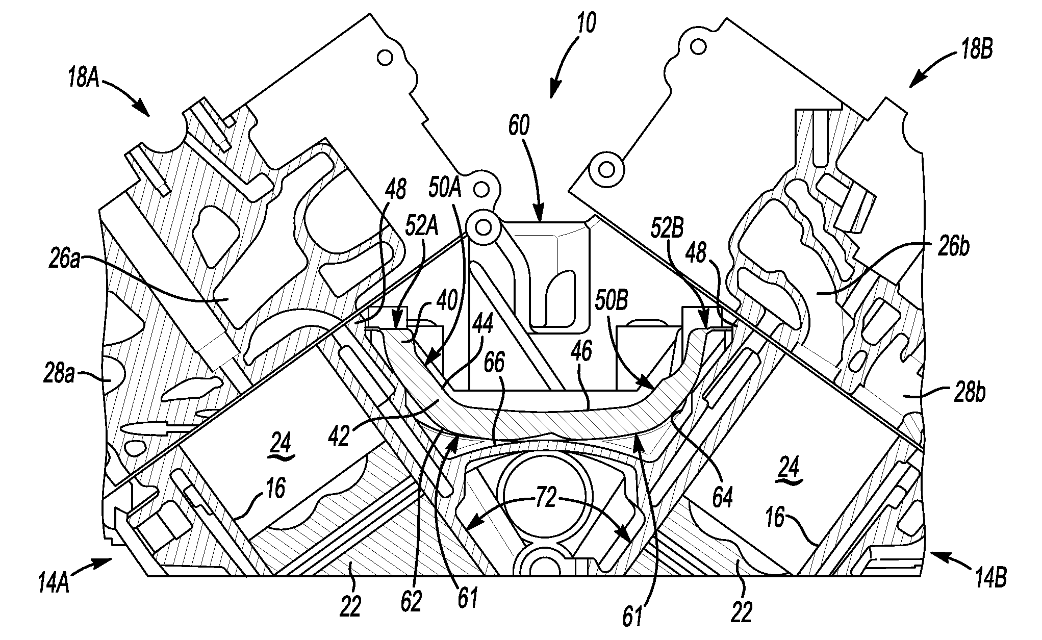
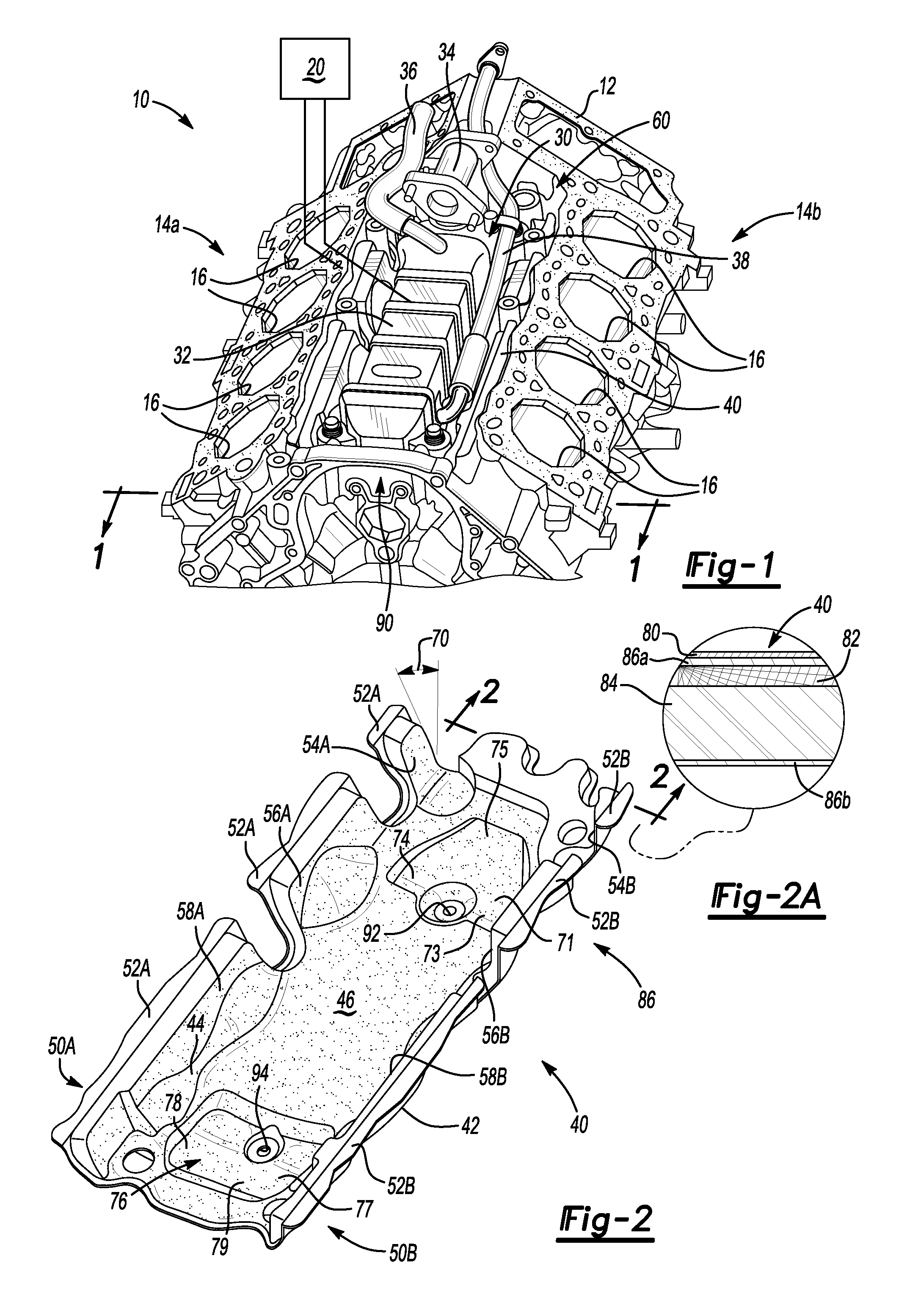
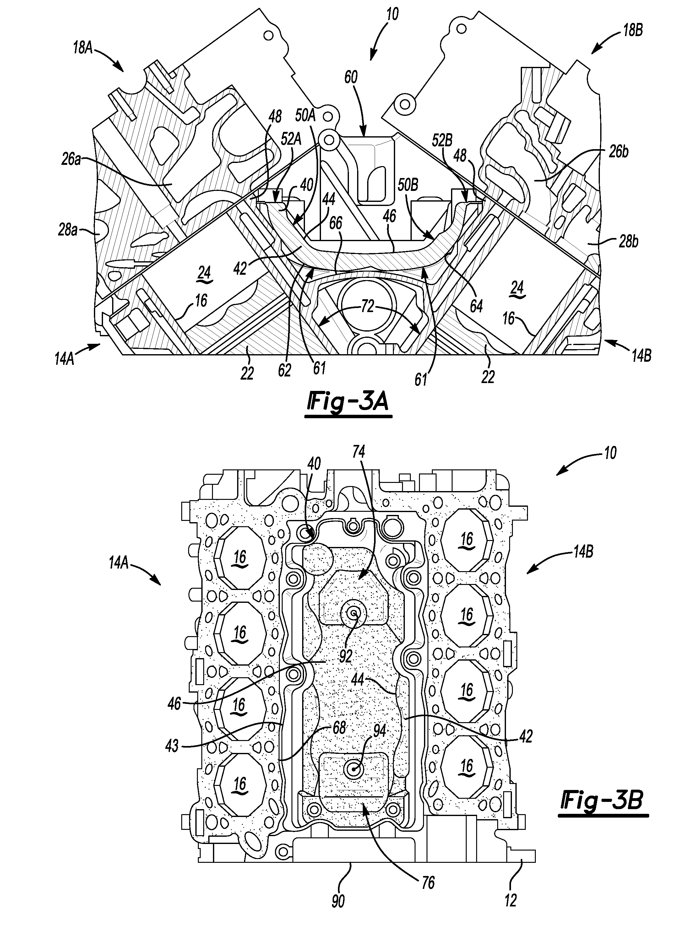
[0023]Referring to the Figures, wherein like reference numbers refer to the same or similar components throughout the several views, there is shown in FIG. 1 an internal combustion engine assembly, presented herein in an exemplary embodiment as a four-stroke cycle, turbocharged and intercooled diesel engine, indicated generally at 10. The engine assembly 10 includes a turbocharger device 20 and exhaust gas recirculation (EGR) system 30 in operative communication therewith. Notably, the engine 10, turbocharger 20, and EGR system 30 shown in FIG. 1 have been greatly simplified, it being understood that further information regarding such systems may be found in the prior art. Furthermore, it should be readily understood that FIG. 1 is merely a representative application by which the present invention may be practiced. As such, the present invention is by no means limited to the particular engine configuration of FIG. 1. Finally, the drawings presented herein, i.e., FIGS. 1 through 3B, ...


PUM


Abstract

A valley shield operable as a noise, fluid, and heat barrier is provided for use with an engine assembly having an engine block with two cylinder banks defining an interbank valley therebetween, and two cylinder heads secured thereto. The valley shield has a unitary body including a base with two laterally spaced side portions extending angularly outward therefrom. The body is configured to pressably fit into place proximate to the valley, between the two cylinder banks, and be secured therein by the cylinder heads. The base is oriented immediately adjacent to the interbank valley and is contoured to define an air pocket therebetween. Each lateral side portion includes a flange extending laterally therefrom to directly engage with the perimeter of the interbank valley, providing an acoustic seal therebetween. The base defines two longitudinally displaced trough portions each defining drain holes and configured to allow for gravitational evacuation of fluid therefrom.

Description

CLAIM OF PRIORITY[0001]This application claims priority to U.S. Provisional Patent Application No. 60 / 956,029, filed on Aug. 15, 2007, which is hereby incorporated by reference in its entirety.TECHNICAL FIELD[0002]The present invention relates generally to internal combustion engines, and more particularly to thermal valley shields for V-type engine block assemblies having an interbank valley defined between the two engine cylinder banks.BACKGROUND OF THE INVENTION[0003]“V-type” internal combustion engine (ICE) assemblies are traditionally defined by an engine block having a pair of outwardly angled cylinder banks with inside walls that define an interbank valley therebetween. Each cylinder bank of a typical V-type over-head valve ICE defines a cylinder bore having a piston reciprocally movable therein. The piston and cylinder bore cooperate with a portion of a cylinder head to form a variable volume combustion chamber. The cylinder head defines intake ports through which air, provi...

Claims


Application Information

Patent Timeline
Patent Type & Authority Patents(United States)
IPC IPC(8): F02B77/00
CPCF02B77/11F02M25/0731Y02T10/121F02M26/28
Inventor HAZELTON, GARY J.READ, IAIN J.
Owner GM GLOBAL TECH OPERATIONS LLC
Why Eureka
Try Eureka