Axial trim for dirty service valve

a service valve and axial trim technology, which is applied in the direction of valve operating means/releasing devices, functional valve types, transportation and packaging, etc., can solve the problems of loss of both flow and control within the valve, the susceptibility of fluid passages defined by disk stacks or valve cages to clogging, and the potential problems of affecting the flow of the valve, etc., to achieve the effect of increasing the cv capacity, prolonging the stroke length

Active Publication Date: 2011-06-14
CONTROL COMPONENTS INC
View PDF12 Cites 13 Cited by
  • Summary
  • Abstract
  • Description
  • Claims
  • Application Information

AI Technical Summary

Benefits of technology

[0012]In accordance with the present invention, there is provided a dirty service valve including an axial trim which, as a result of its structural attributes and extended stroke length, provides increased Cv capacity relative to valve plug size in comparison to existing prior art designs. In accordance with one embodiment of the present invention, the axial trim integrated into the valve of the present invention is configured to provide a linear flow characteristic. In accordance with an alternative embodiment of the present invention, the axial trim may be configured to provide a non-linear flow characteristic which, coupled with the extended stroke length thereof, provides improved flow control in addition to increased Cv capacity. The axial trim possessing the above-described structural and functional attributes may also be integrated into an axial body or housing, thus making the use of rotary actuators in conjunction with the axial trim more feasible.

Problems solved by technology

The channeling of erosive fluids through linear displacement valves including flow control elements which comprise stacked disk designs or valve cage / cartridge designs gives rise to certain potential problems.
More particularly, the potential problems lie in the susceptibility of the fluid passages defined by such disk stacks or valve cages becoming plugged by dirt or other debris in the fluid stream.
In this regard, the blocking of the fluid passages of the flow control element with debris often causes a loss of both flow and control within the valve.
Though these existing notch style axial trim valves are well suited for use with erosive fluids and provide high flow resistance, they possess certain deficiencies which detract from their overall utility.
One such deficiency relates to a lack of flow control.
These control problems are attributable to the fact that currently known notch style axial trims possess a linear flow characteristic (i.e., Cv vs. axial trim stroke length).
Another deficiency lies in the reduced Cv capacity of currently known notch style axial trims, such reduced capacity being attributable to their design coupled with the relatively short stroke length thereof within the valve.
Additionally, axial trims, including the notch style axial trims discussed above, have not successfully been integrated into axial style bodies, and thus are not well suited for use in conjunction with rotary actuators.

Method used


Image

  • Axial trim for dirty service valve
  • Axial trim for dirty service valve
  • Axial trim for dirty service valve

Examples


Embodiment Construction

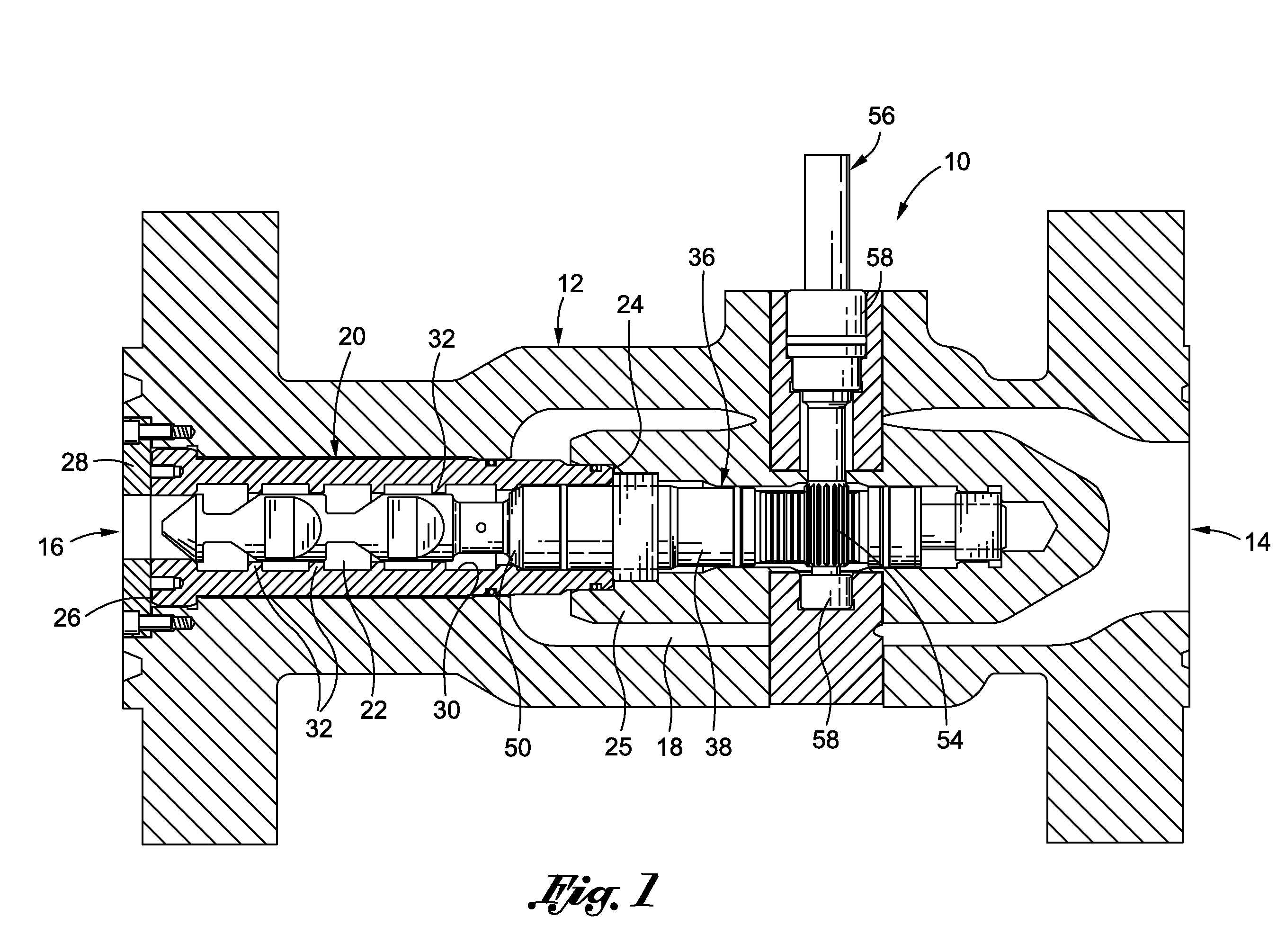
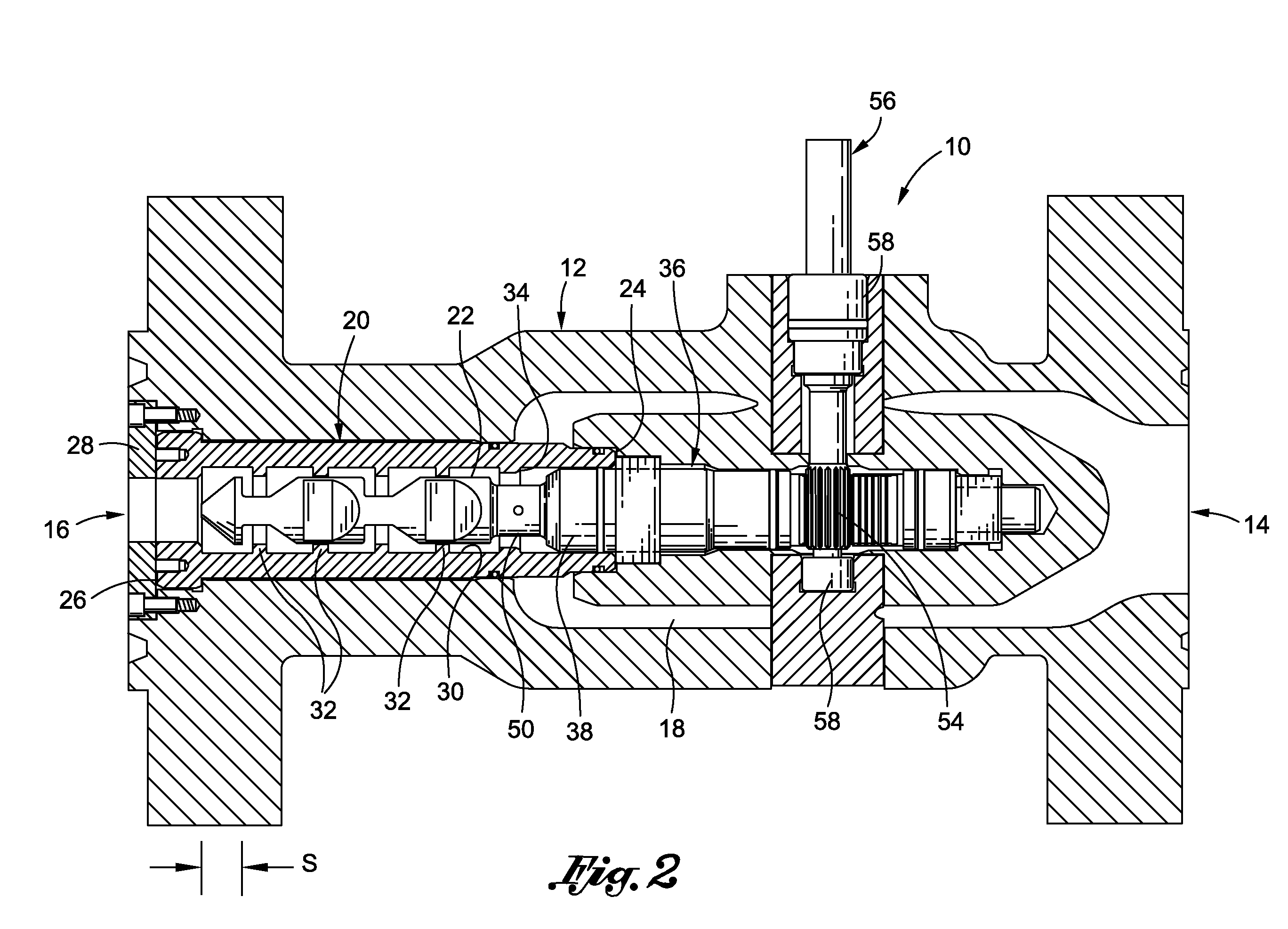
[0023]Referring now to the drawings wherein the showings are for purposes of illustrating preferred embodiments of the present invention only, and not for purposes of limiting the same, FIGS. 1 and 2 depict an axial trim valve 10 constructed in accordance with a first embodiment of the present invention. As will be discussed in more detail below, the axial trim valve 10 is specifically suited for use in relation to “dirty service” applications wherein a dirty or erosive fluid is channeled therethrough.

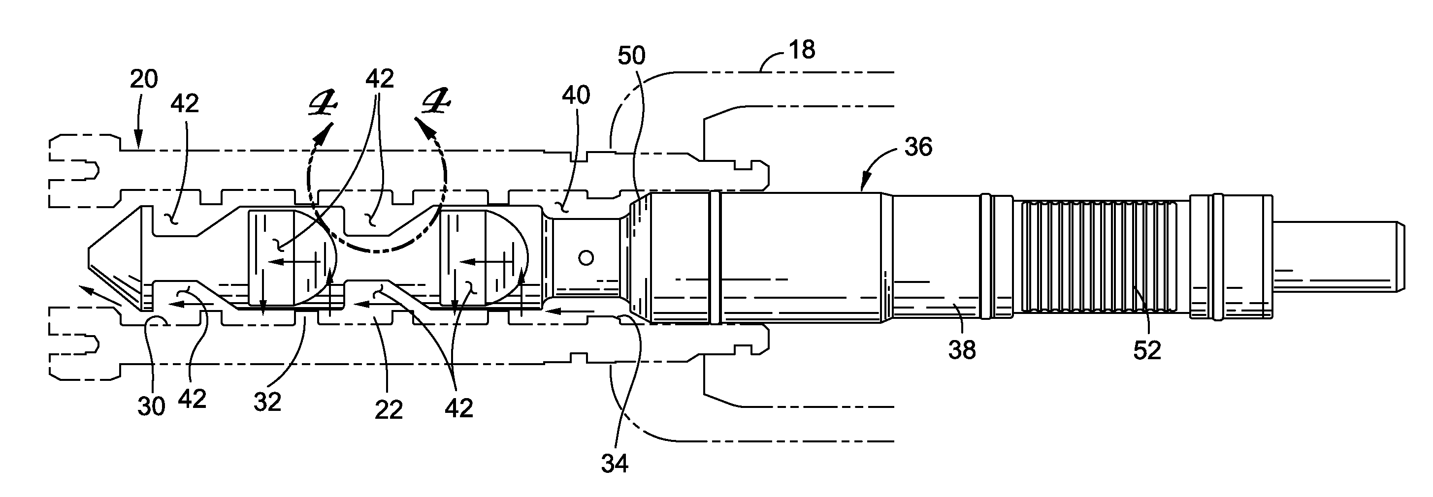
[0024]The valve 10 comprises a housing 12 which defines a fluid inlet 14 and a fluid outlet 16. The fluid inlet 14 fluidly communicates with an inlet passage 18 which is defined by the housing 12. Disposed within the housing 12 is a generally cylindrical, tubular valve cage 20 which defines an outlet passage 22 fluidly communicating with the fluid outlet 16. The inlet passage 18 fluidly communicates with the outlet passage 22 via a plurality of openings 23 which are disposed within and...


PUM


Abstract

In accordance with the present invention, there is provided a dirty service valve including an axial trim which, as a result of its structural attributes and extended stroke length, provides increased Cv capacity relative to valve plug size in comparison to existing prior art designs. In accordance with one embodiment of the present invention, the axial trim integrated into the valve of the present invention is configured to provide a linear flow characteristic. In accordance with an alternative embodiment of the present invention, the axial trim may be configured to provide a non-linear flow characteristic which, coupled with the extended stroke length thereof, provides improved flow control in addition to increased Cv capacity. The axial trim possessing the above-described structural and functional attributes may also be integrated into an axial body or housing, thus making the use of rotary actuators in conjunction with the axial trim more feasible.

Description

CROSS-REFERENCE TO RELATED APPLICATIONS[0001]Not ApplicableSTATEMENT RE: FEDERALLY SPONSORED RESEARCH / DEVELOPMENT[0002]Not ApplicableBACKGROUND OF THE INVENTION[0003]1. Technical Field of the Invention[0004]The present invention relates generally to flow control devices, and more particularly to a valve including an axial style trim which is adapted to facilitate a pressure drop along the axis of the trim and is well suited for use in conjunction with erosive fluids.[0005]2. Description of the Related Art[0006]As is known in the fluid flow control field, the control of erosive and cavitational forces is a primary objective of the design of many high pressure valves. There is currently known in the prior art valves which include shafts and plugs that are linearly displaced during normal operation of the valve. Within these valves, which are often referred to as linear displacement valves, the valve plug of the valve is disposed and moveable within a flow control element such as a dis...

Claims


Application Information

Patent Timeline
Patent Type & Authority Patents(United States)
IPC IPC(8): F16K47/00
CPCF16K47/04F16K1/12Y10T137/86791
Inventor NEWTON, RAYMOND R.SMIRL, PAUL A.
Owner CONTROL COMPONENTS INC
Why Eureka
Try Eureka