Hydraulic self-sealed plunger oil-well pump

A technology of oil well pump and plunger, which is applied in the lifting field of oil mining machinery, can solve the problems of increasing the cost of crude oil extraction, and achieve the effects of reducing energy consumption, increasing stroke length, and improving pump efficiency

Inactive Publication Date: 2007-01-10
DAQING OILFIELD CO LTD
View PDF0 Cites 4 Cited by
  • Summary
  • Abstract
  • Description
  • Claims
  • Application Information

AI Technical Summary

Problems solved by technology

The above problems can only be solved by pulling out the rod string or tubing string, which increases the cost of crude oil extraction

Method used


Image

  • Hydraulic self-sealed plunger oil-well pump
  • Hydraulic self-sealed plunger oil-well pump
  • Hydraulic self-sealed plunger oil-well pump

Examples


Embodiment Construction

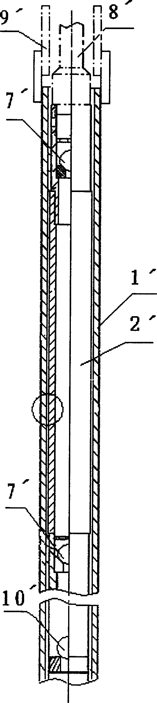
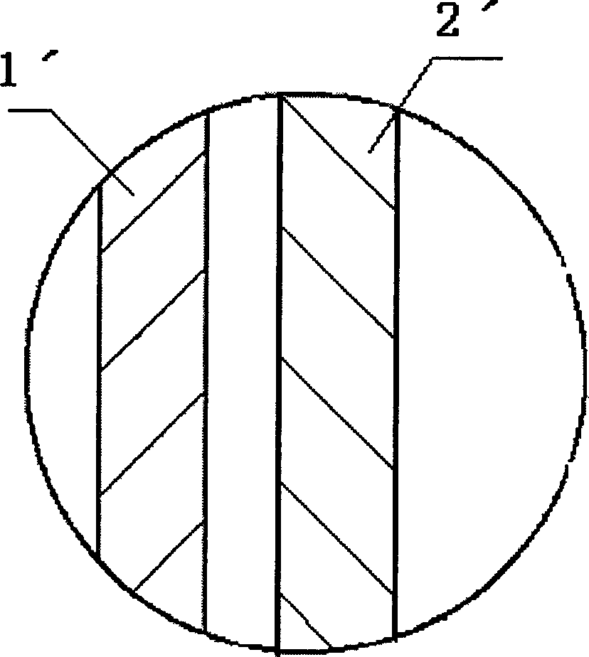
[0012] Conventional hydraulic plunger pump, see figure 2 and Figure 2A , including pump barrel 1', plunger 2', swimming valve 7', and fixed valve 10', wherein the swimming valve 7' is connected to the plunger 2' through a screw thread, and the plunger 2' is connected to the pump Cylinder 1' clearance fit; when in use, the pump cylinder 1' is connected with the oil pipe 9', the plunger 2' is connected with the sucker rod 8', and the sucker rod 8' drives the plunger 2' and the swimming valve 7' to be opposite Pump barrel 1' moves, swimming valve 7' opens on downstroke, lift fluid enters between fixed valve 10' in pump cylinder 1' and plunger 2', on upstroke, swimming valve 7' Closed, the oil is lifted to the surface through the plunger.

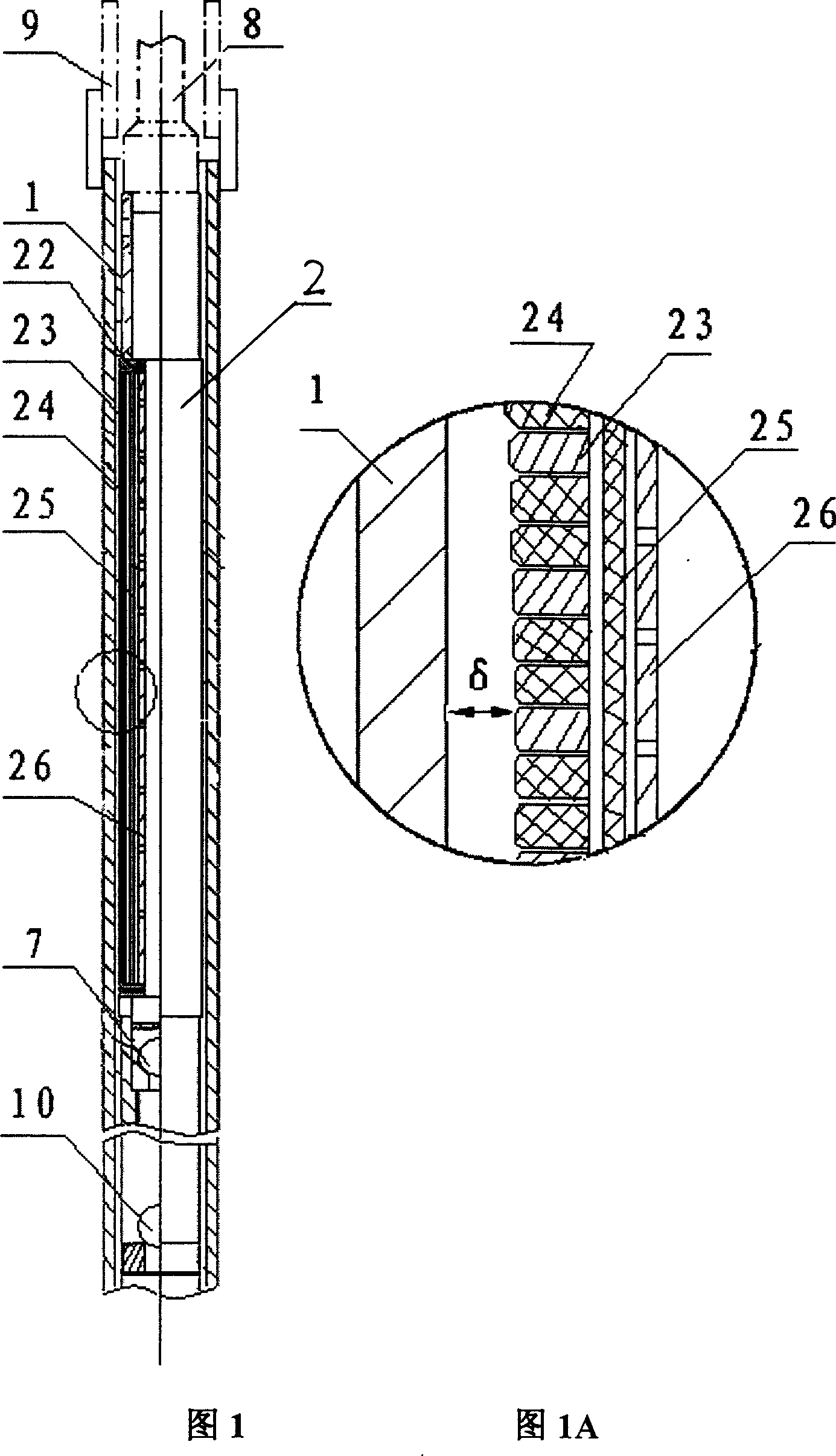
[0013] Referring to Fig. 1, the hydraulic self-sealing plunger oil well pump of the present invention also includes components such as a pump barrel 1, a plunger 2, a movable valve 7 and a fixed valve 10, and the movable valve 7 is connected...


PUM


Abstract

The invention provides a hydraulic self-sealing plunger oil pump, for thoroughly solving the friction problem between sucker rod and oil pipe, comprising plunger, pump barrel and traveling valve, where central rod sieve tube of the plunger is jacketed with a seal elastomer layer, the seal elastomer is jacketed with rigid metal ring and elastic seal ring. In the up-stroke course of the oil pump, the high pressure in the plunger acts through the seal elastomer onto the wearable elastic seal ring to reduce clearance between the seal ring and the pump barrel, strengthening seal and reducing leakage; in the down-stroke course, the pressures at two ends of the plunger are the same, the wearable seal ring contracts, increasing the clearance and reducing down-going resistance of the plunger. And the seal ring structure of the invention is applied to all hydraulic-plunger or multi-plunger pumps, having advantages of reducing the leakage of pump, raising volume of pump and efficiency of pump, etc.

Description

Technical field: [0001] The invention belongs to the lifting field of petroleum exploitation machinery, in particular to a plunger oil well pump of a pumping unit, which is a hydraulic plunger oil well pump with a self-sealing function. Background technique: [0002] Existing pumping unit plunger pump (see figure 2 ) During the oil pumping process, due to the friction between the plunger 2' and the pump barrel 1', the sucker rod 8' bends and rubs against the oil pipe 9' when it goes down, especially in heavy oil and oil containing When the amount of sand is large and the flooding fluid containing polymer is pumped, the viscoelasticity of the fluid increases, and the downward resistance of the plunger increases. It increases as the height increases, and increases as the gap between the plunger 2' and the pump barrel 1' decreases. After the friction between the plunger and the pump barrel increases, the sucker rod bends and rubs against the oil pipe during the downstroke, ca...

Claims


Application Information

Patent Timeline
Patent Type & Authority Applications(China)
IPC IPC(8): F04B53/02F04B47/02E21B43/00
Inventor 韩修廷王秀玲侯宇侯德艳刘春天梅小娥
Owner DAQING OILFIELD CO LTD
Why Eureka
Try Eureka