Anti-airlock pump

a technology of anti-airlock and pump, which is applied in the direction of priming pump, machines/engines, liquid fuel engines, etc., can solve the problems of reducing the pumping performance, affecting the pumping efficiency, and sometimes malfunctioning, so as to achieve the effect of not reducing the pumping efficiency

Active Publication Date: 2012-08-16
LIBERTY PUMPS
View PDF4 Cites 6 Cited by
  • Summary
  • Abstract
  • Description
  • Claims
  • Application Information

AI Technical Summary

Benefits of technology

[0010]The problem of plugging of a bleed hole in the volute of a pump by particles of solids present in a liquid being pumped is solved by providing the bleed hole in a particular region relative to the energetic element of the pump. In a pump comprised of a volute and an impeller (as the energetic element) having secondary back vanes (also known as “pump-out” or “slinger” vanes) on the side of the impeller that is proximate to the volute wall, a bleed hole is provided in a particular region relative to the pump out vanes and the volute wall. The Applicant's experimental testing has demonstrated that the optimal location of the bleed hole is approximately midway along the length of the pump out vanes, as will be subsequently explained in further detail herein. The bleed hole location enables it to be of a small size so as to not reduce pump efficiency, while not becoming plugged with debris.

Problems solved by technology

However, malfunctions do sometimes occur, and in such circumstances, if the pump is not turned off and does suck air, then a problem may occur the next time the pump is restarted.
A liquid pump is not designed to move air, and the presence of air in the volute chamber will greatly reduce the pumping performance of the pump.
Under these circumstances, the pump will not develop adequate head pressure to overcome the closing force of the check valve and the static force of the liquid column acting on it.
However, when solid debris, such as solids from macerated toilet effluent, or from a sewage grinder pump is suspended in the liquid, the bleed hole can become blocked with debris particles.
This renders it ineffective.
However, in some installations, this is not practical from a cost or time standpoint.
Additionally, for a sewage grinder pump, or a pump that is part of a macerating apparatus for a toilet, because of the unsavory contents of the liquid, this is an unpleasant maintenance task that is to be avoided.

Method used


Image

  • Anti-airlock pump
  • Anti-airlock pump
  • Anti-airlock pump

Examples


Embodiment Construction

[0020]For a general understanding of the present invention, reference is made to the drawings. In the drawings, like reference numerals have been used throughout to designate identical elements.

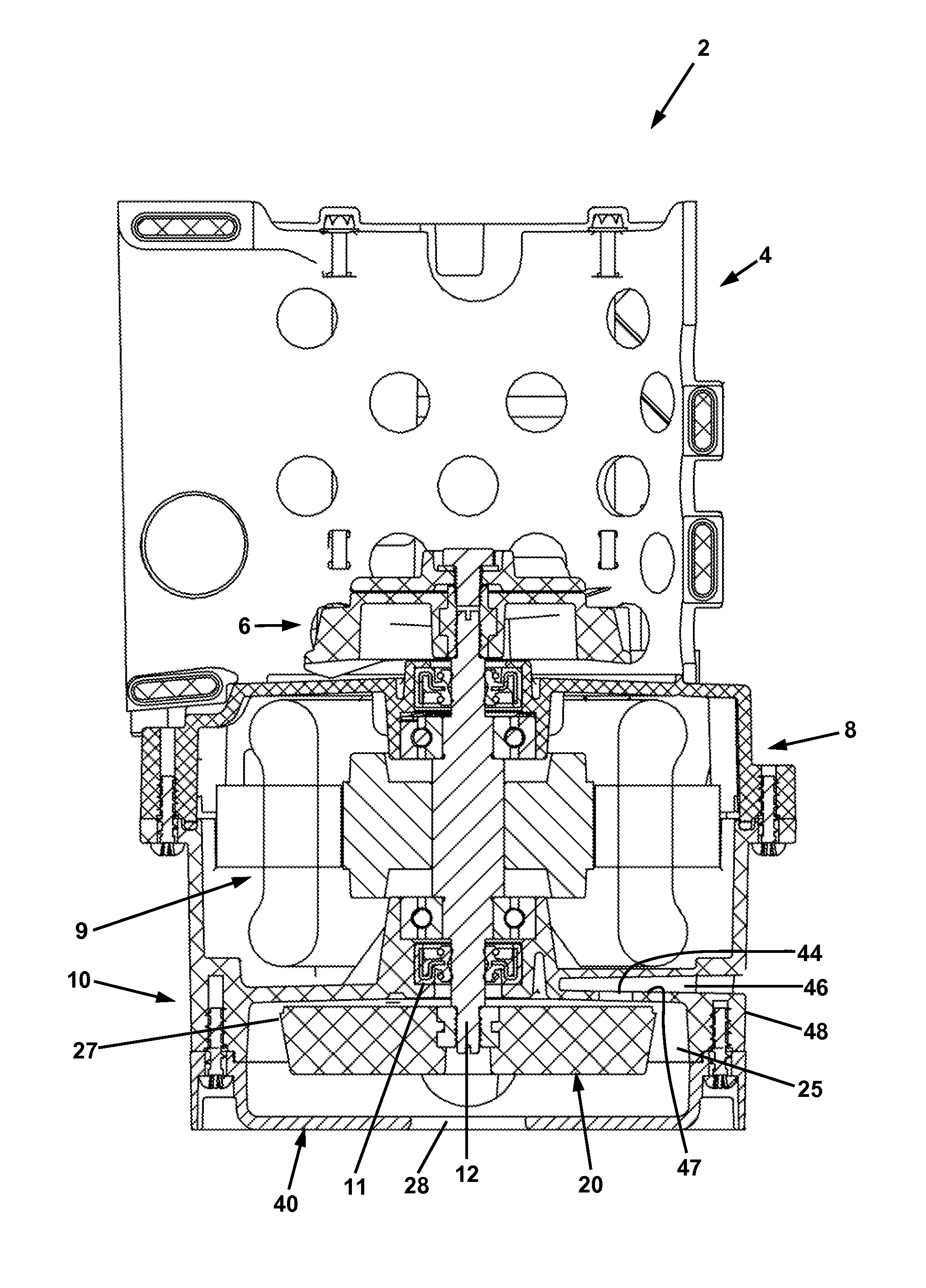
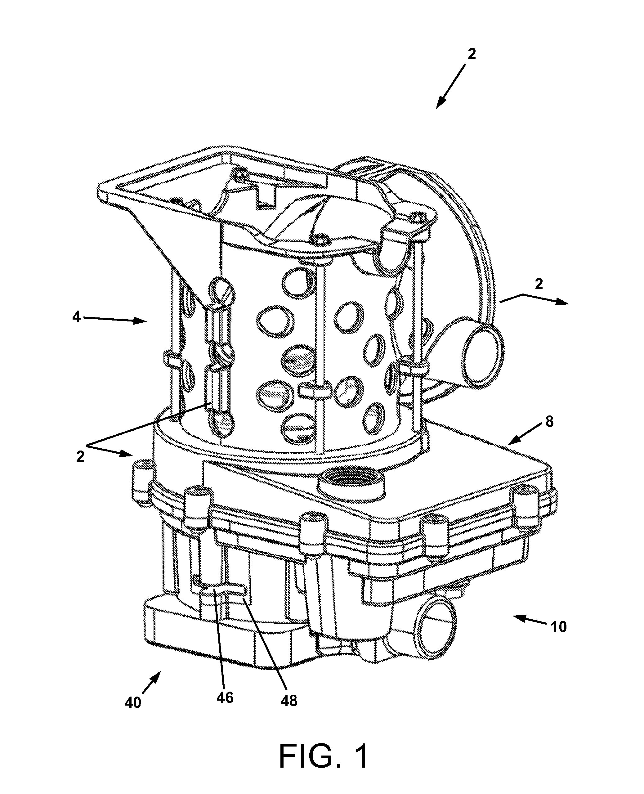
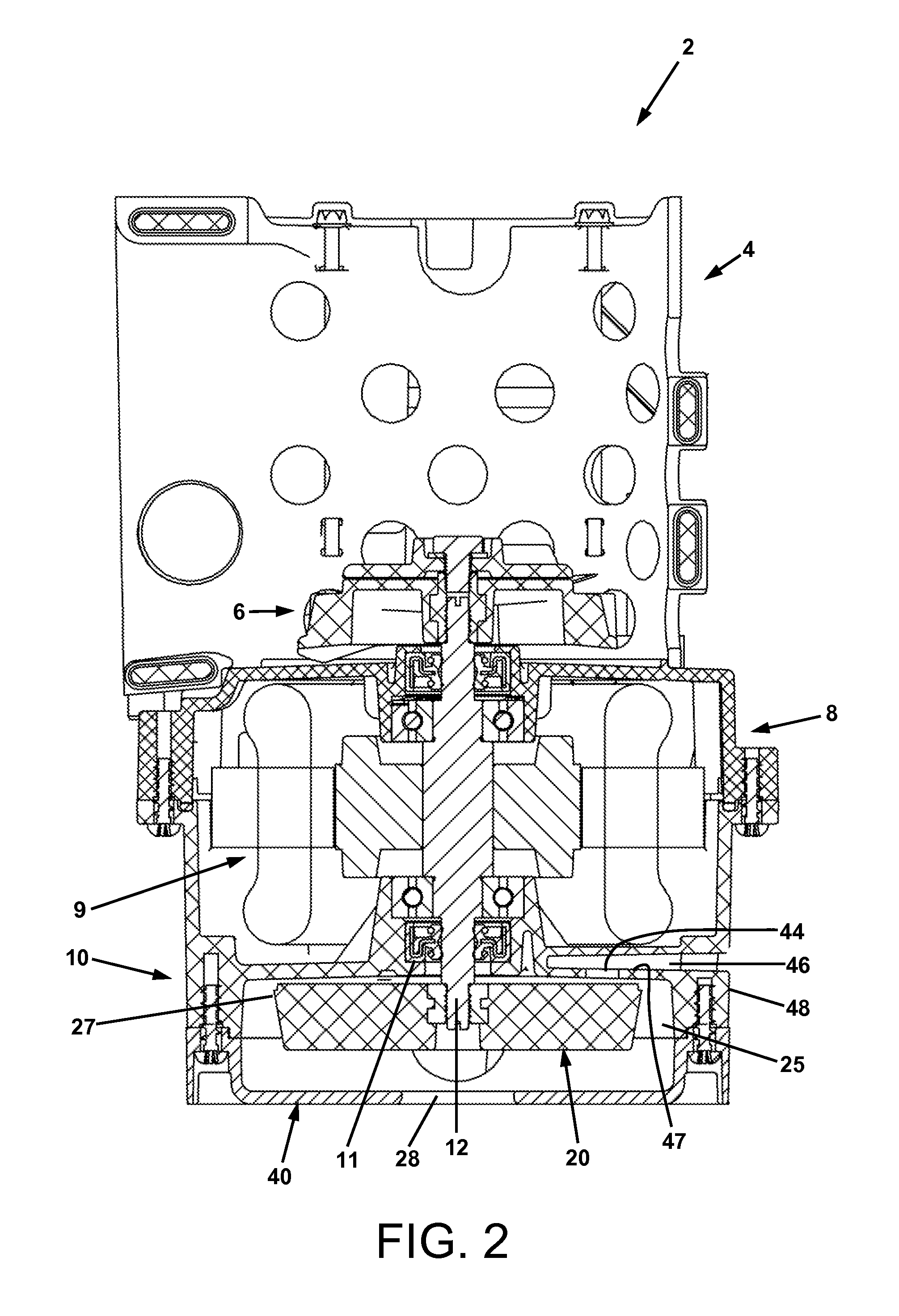
[0021]Referring to FIGS. 1-4, a macerating unit 2 is shown, which is comprised of an intake basket 4, a cutter 6, and a pump 10. The pump 10 is comprised of a rotary shaft 12 operatively connected to an impeller 20 that is contained in a volute 40. The shaft 12 may be driven by a motor 9, which may be contained in a motor enclosure 8.

[0022]The impeller 20 typically comprises a flange 22 with vanes 24 on the processing side that impart momentum into the processing fluid, thereby pumping it. On the opposite side 25 of the impeller flange 22 are smaller vanes 26 that act as slingers to prevent debris from contacting the shaft seal 11. These slinger or pump out vanes 26 create a pressure gradient on the top side 25 of the impeller 20. The shaft seal 11 is at the lowest pressure, which increases g...


PUM


Abstract

A pump having anti-airlock provisions. The pump is comprised of a volute comprised of a volute wall, and an impeller comprising back vanes on a side of the impeller that is proximate to the volute wall, with the back vanes having a length extending radially outwardly along the impeller. A bleed hole is formed in the volute wall in communication with the portion of the volute between the back vanes and the volute wall, and the exterior of the volute, such that the bleed hole is located midway along the length of the back vanes. When the pump is operating with air, liquid, or a combination of air and liquid in the volute, the bleed hole is under positive pressure with respect to the exterior of the volute. The bleed hole may be in communication with the exterior of the volute through a lateral tunnel formed in the pump.

Description

CROSS-REFERENCE TO RELATED PATENT APPLICATIONS[0001]This application is related to commonly owned copending application Ser. No. 13 / 027,878, filed on the same day as this application under Docket No. LIB102, and titled “MACERATING APPARATUS AND METHOD,” the disclosure of which is incorporated herein by reference.BACKGROUND[0002]1. Field of the Invention[0003]Centrifugal and other liquid pumps, and provisions to prevent air locking of such pumps.[0004]2. Description of Related Art[0005]A pump is a device used to transport liquid from a lower to a higher elevation, or from a lower pressure state to a higher pressure state. Typically, an electric motor is used to spin an impeller inside a volute casing transferring energy to the liquid. In many instances, a pump is submerged in a reservoir of liquid, and its discharge is connected to a pipe that is used to convey the liquid to a higher elevation or higher pressure vessel.[0006]A backflow prevention device such as a check valve is used ...

Claims


Application Information

Patent Timeline
Patent Type & Authority Applications(United States)
IPC IPC(8): F01D25/24
CPCF04D29/2288F04D9/002
Inventor POHLER, DONALD M.HEINSLER, MATTHEW S.
Owner LIBERTY PUMPS
Why Eureka
Try Eureka