Electric tracing band for oil well

An electric heating and oil well technology, applied in the direction of heating element shape, etc., can solve the problems of increasing the volume, weight and cost of equipment, reducing the heating efficiency of heating cables, and the weight of copper core iron cables, etc., to improve the electrothermal conversion efficiency and light weight , the effect of improving flexibility

Inactive Publication Date: 2014-05-21
ANBANG ELECTRICAL GRP
View PDF0 Cites 6 Cited by
  • Summary
  • Abstract
  • Description
  • Claims
  • Application Information

AI Technical Summary

Problems solved by technology

Due to the high operating frequency of the transformer, the loss of the transformer increases, which reduces the overall heating efficiency of the heating cable to a certain extent, and also increases the volume, weight and cost of the equipment
In addition, because this copper core iron cable is heavy and bulky, it is inconvenient to operate during the construction process.

Method used


Image

  • Electric tracing band for oil well

Examples


Embodiment 1

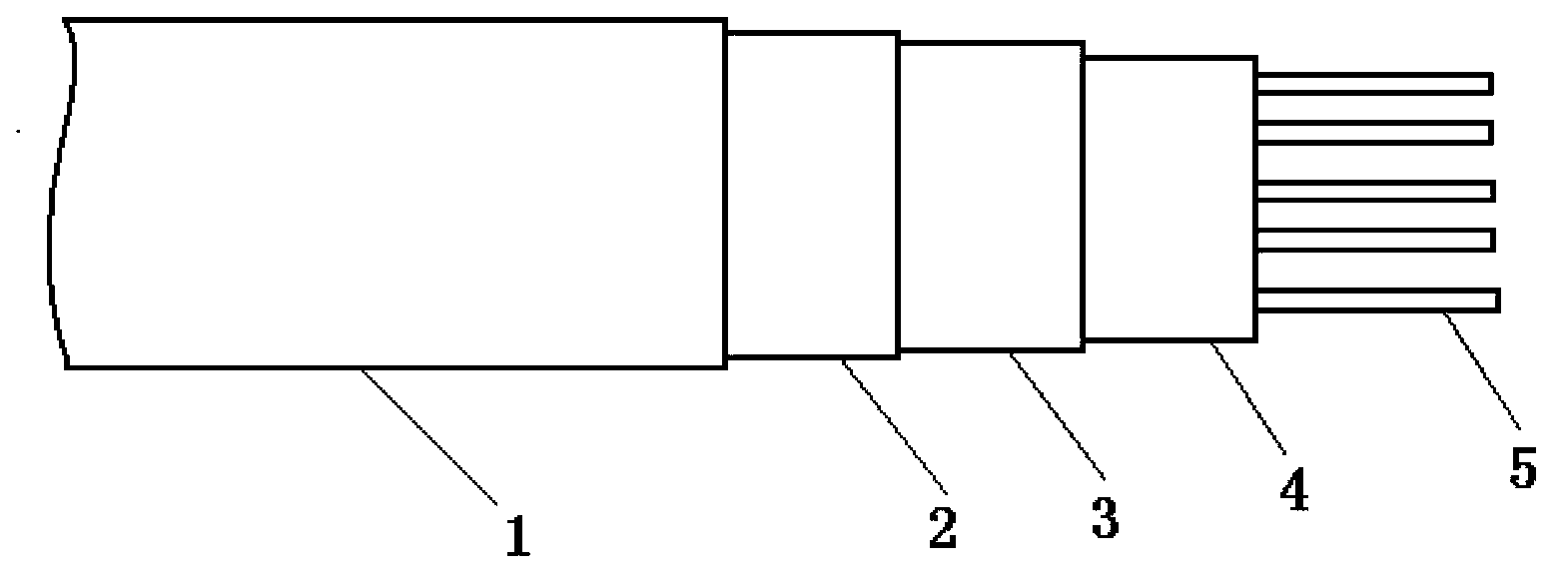
[0024] As shown in Figure 1, an electric heating tape for oil wells, the electric heating tape includes a core tape 4, the core tape 4 is composed of five carbon fiber heating wires 5 arranged in parallel and filled with PTC conductive carbon fiber heating wires 5 It consists of a filler, and the core band 4 is sequentially covered with an insulating layer 3 made of silicone rubber, a shielding layer 2 made of a laminated aluminum foil material, and a protective layer 1.

Embodiment 2

[0026] An electric heating tape for oil wells. The electric heating tape comprises a core tape 4 composed of five carbon fiber heating wires 5 arranged in parallel and a PTC conductive filler filling the carbon fiber heating wires 5. The belt 4 is successively wrapped with an insulating layer 3 made of polyvinyl chloride plastic, a shielding layer 2 made of a laminated copper foil material, and a protective layer 1.

Embodiment 3

[0028] The core tape filler PTC conductive filler of the electric heating tape is composed of polyvinylidene fluoride, magnesium hydroxide, and antioxidant 1010 at 1:4:0.01.


PUM


Abstract

The invention discloses an electric tracing band for an oil well. The electric tracing band comprises a core band which is formed by five parallel wires and PTC conductive fillers filled among the wires. The outside of the core band is covered with an insulation layer, a shielding layer and a protection layer successively. According to the electric tracing band, the heating body is made of novel carbon fibers, the weight is low, construction is facilitated, the electro-thermal conversion efficiency of the heating cable is improved, and automatic compensation and automatic temperature adjustment are achieved.

Description

Technical field [0001] The invention relates to a heating cable, in particular to a self-limiting temperature electric tracing cable used in oil wells. technical background [0002] The working principle of the self-limiting temperature electric heating cable is to fill the PTC polymer conductive plastic between the two parallel wires as the core tape. The polymer plastic is the matrix material and acts as the framework and filler carrier. The inorganic conductor filler is the current carrier in the insulator. It forms a connected conductive network and acts as a current channel. When the power is turned on, the current flows through one of the wires through the core band to the other wire to form a loop. The core band generates heat after being energized to compensate for the heat dissipation loss of the pipeline. When the temperature of the conductive plastic increases, it expands by heating, causing part of the current channel network to be gradually disconnected, and the cur...

Claims


Application Information

Patent Timeline
Patent Type & Authority Applications(China)
IPC IPC(8): H05B3/56
Inventor 李贻连
Owner ANBANG ELECTRICAL GRP
Why Eureka
Try Eureka