Sliding device for a vehicle seat provided with an improved locking arrangement

a technology of sliding device and locking arrangement, which is applied in the direction of vehicle seats, vehicle components, movable seats, etc., can solve the problems of user dissatisfaction, jamming of the respective locking assembly, and penetration into the sliding device track, so as to avoid the risk of locking assembly jamming and increase the length of the locking pin stroke

Active Publication Date: 2021-08-12
MARTUR ITAL SRL
View PDF0 Cites 4 Cited by
  • Summary
  • Abstract
  • Description
  • Claims
  • Application Information

AI Technical Summary

Benefits of technology

[0033]This arrangement allows to obtain a compact structure, which turns out to be advantageous in packaging the sliding device with respect to the external release systems proposed in the prior solutions, in which the connecting members of the releasing assembly are arranged at least partially outside the respective tracks.
[0034]Moreover, thanks to the substantially translational movement of the locking pins, the risk that the locking pins get stuck against the edge of the apertures of the lower rails is avoided, thus avoiding the risk of jamming of the locking assemblies.
[0035]In addition, the length of the stroke of the locking pins can be increased with respect to traditional locking arrangements, thus ensuring a correct disengagement of the locking pins from the apertures of the lower rails.

Problems solved by technology

Moreover, as they are at least partially arranged outside the tracks of the sliding device, such connecting members are exposed to dust and dirt, which may accumulate between the moving parts of these connecting members and cause malfunctioning thereof.
Such dust and dirt may also penetrate into the tracks of the sliding device and interfere with the movement of the locking pins from their locking configuration to their unlocking configuration, and vice versa.
Usual malfunctioning issues include increased release efforts, increased sliding efforts and noise issues, which may trigger users' dissatisfaction.
As the fork-shaped elements of the connecting members move along an arc-shaped path, the locking pins will move along an arc-shaped path as well, which can entail remarkable problems.
As a result, during their movement the locking pins may get stuck against the edge of the respective apertures of the lower rails, thus causing jamming of the respective locking assembly.
Moreover, due to the movement along an arc-shaped path, the length of the stroke of the locking pins is limited, which allows little margin for guaranteeing that the locking pins correctly move out of the apertures of the lower rails when actuated by the connecting members of the release assembly.
Furthermore, when designing the locking arrangement, enough room has to be provided for the rotational movement of the connecting members and of the locking pins.

Method used


Image

  • Sliding device for a vehicle seat provided with an improved locking arrangement
  • Sliding device for a vehicle seat provided with an improved locking arrangement
  • Sliding device for a vehicle seat provided with an improved locking arrangement

Examples


Embodiment Construction

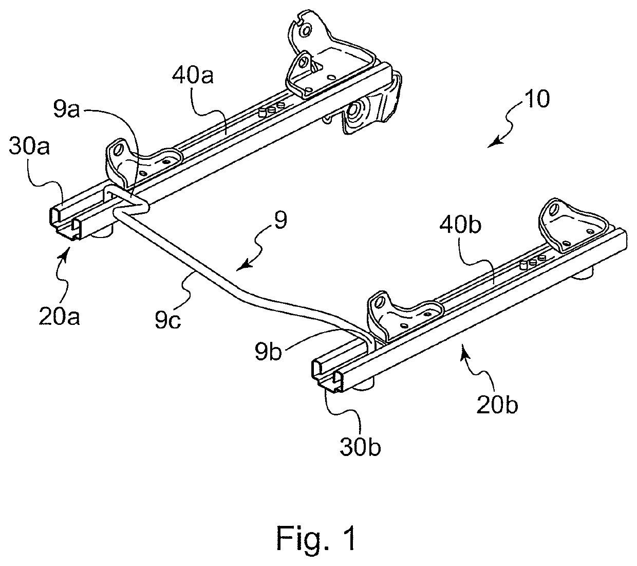
[0057]With reference to FIG. 1, a sliding device 10 according to the invention is shown.

[0058]In a per se known manner, the sliding device 10 comprises a pair of parallel tracks 20a, 20b, each comprising a lower rail 30a, 30b, intended to be attached to the vehicle floor, and an upper rail 40a, 40b, intended to be attached to the frame of a vehicle seat.

[0059]Each upper rail 40a, 40b is constrained to the respective lower rail 30a, 30b, but can slide relative to said lower rail.

[0060]In order to selectively allow / prevent a sliding movement of the upper rails relative to the lower rails of the tracks 20a, 20b, a locking arrangement is provided. Said locking arrangement comprises two locking assemblies, one for each track 20a, 20b.

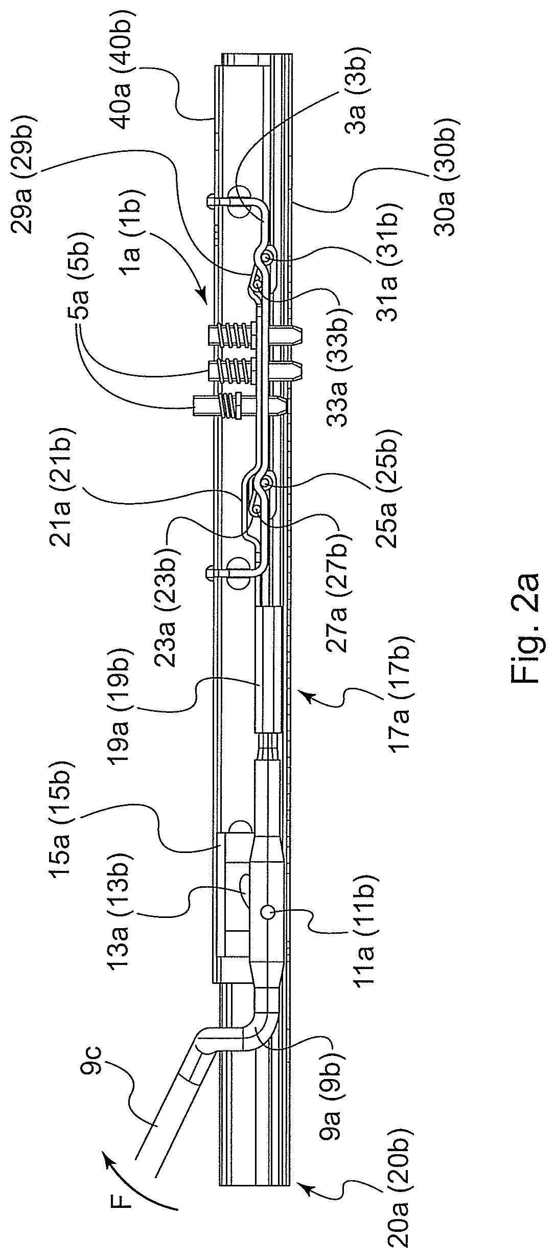
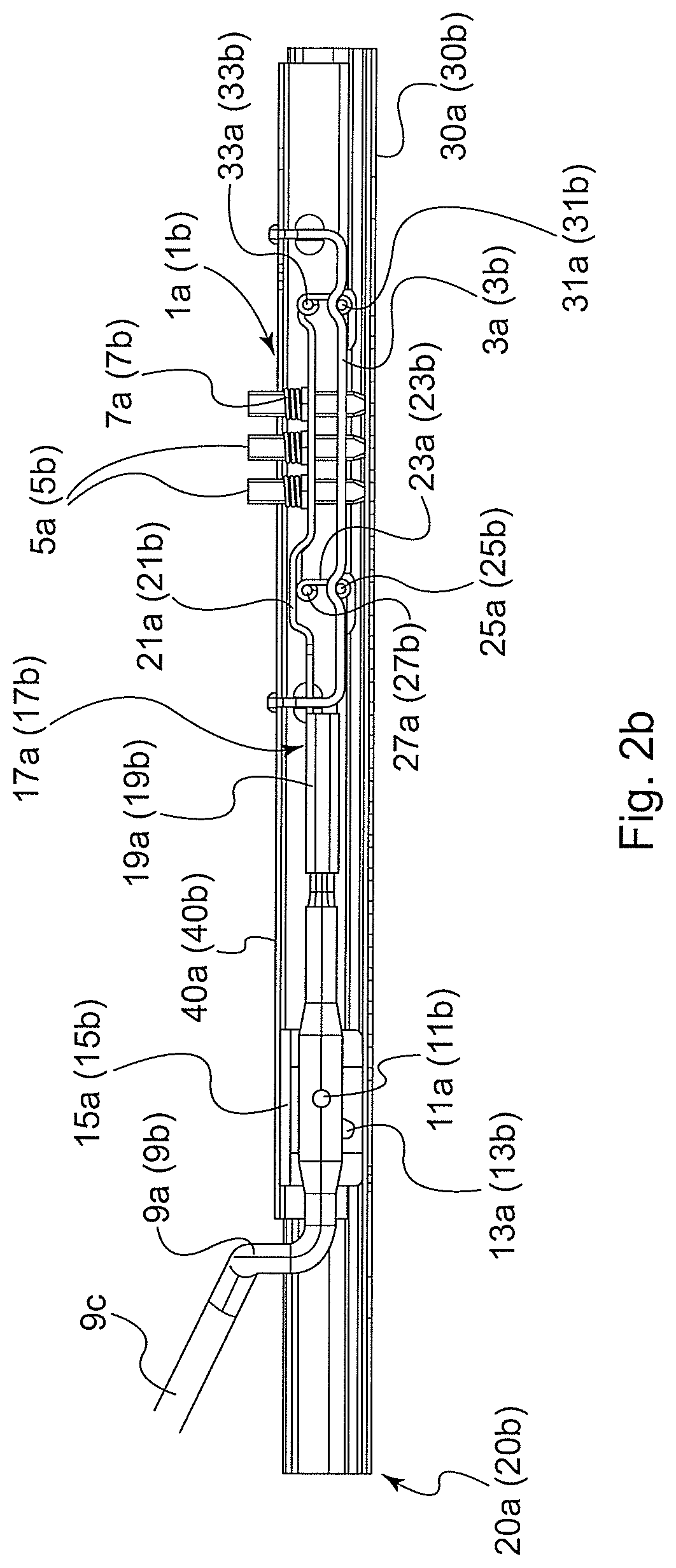
[0061]One of said locking assemblies can be seen in detail, for instance, in FIGS. 4a -4b. It is to be intended that the other locking assembly is identical to the one shown in FIGS. 4a-4b.

[0062]Each locking assembly 1a, 1b comprises a support plate 3a, 3b...


PUM


Abstract

A sliding device for a vehicle seat is provided with an improved locking arrangement. The locking arrangement includes a pair of locking assemblies, each including one or more locking pins suitable for locking upper rails of the seat tracks to respective lower rails. The locking arrangement also includes a releasing assembly suitable for driving the locking pins to an unlocking configuration and comprising a releasing member and a pair of connecting members, which are in a force transmission connection with the releasing member and with the locking pins of a respective locking assembly. The connecting members are entirely received within the respective tracks, and the releasing assembly is configured to convert a rotational movement of the releasing member into a linear movement of the locking pins of the locking assemblies.

Description

TECHNICAL FIELD[0001]The present invention relates to a sliding device for a vehicle seat provided with an improved locking arrangement.[0002]More particularly, the present invention relates to a sliding device for a vehicle seat provided with a locking arrangement having a compact construction and an improved reliability.BACKGROUND ART[0003]Vehicle seats generally have a sliding function for pushing or pulling the seat cushion in a forward or backward direction, a height adjustment function for adjusting the height of the seat cushion, and a reclining function for adjusting the inclination of the seat backrest relative to the seat cushion.[0004]The aforesaid sliding function is generally implemented by a sliding device which comprises a pair of parallel tracks, each of which comprises a lower rail attached to the vehicle floor and an upper rail attached to the vehicle seat, the upper rail being constrained to the lower rail, but being able to slide relative to said lower rail.[0005...

Claims


Application Information

Patent Timeline
Patent Type & Authority Applications(United States)
IPC IPC(8): B60N2/07
CPCB60N2/0705B60N2/0818B60N2/0715B60N2/0806B60N2/0875B60N2/0881B60N2/0887
Inventor SPAGNOLI, LUIGIÜSTÜNBERK, CAN
Owner MARTUR ITAL SRL
Why Eureka
Try Eureka