Working machine with an electromagnetic converter

a technology of electromagnetic converter and working machine, applied in the field of linear machines, can solve the problems of large loss, reduced power efficiency, and increased loss, and achieve the effects of increasing the area and frequency, increasing the pressure and length of the stroke, and increasing the effect of the area and frequency

Active Publication Date: 2010-03-16
RESONATOR
View PDF17 Cites 4 Cited by
  • Summary
  • Abstract
  • Description
  • Claims
  • Application Information

AI Technical Summary

Benefits of technology

[0020]Calculations and experiments have shown that machines, in accordance with the invention are able to achieve an essentially greater result than it has been possible up to now. The calculations which have been made show that a linear machine according to the invention can be constructed for 30 kW or more output without substantial disadvantages, in view of control and instability.
[0021]It is especially important that the invention permits an increase in working pressure, piston mass, and frequency, or at least one of these dimensions, so that the effect can be increased in relation to corresponding known machines. Most relevant is to increase area and frequency, or pressure and length of stroke.

Problems solved by technology

When the power of the electric motor becomes large, at the same time, the electrical losses become large.
This will reduce the power efficiency.
This will result in resonance.
This means more electric current in the coils than necessary, resulting in greater loss.
In the case of known machines, the length of stroke and the frequency will often be limited, for example, due to a limited speed in view of the slide bearings.
This technique cannot be applied to the manufacture of linear machines with a power output than about 1 kW.
It is alleged here that the piston shall have low mass, with that, this technique can neither be used to manufacture more powerful linear machines.
A lightweight piston will also result in that low energy remains to be stored in the system.
The energy outlet of the load will then result in that the system becomes overdamped, something that is exceptionally demanding in view of the controlling of the force on the piston.
First of all, this solution is complicated to construct and to maintain.
Furthermore, it will have a very short stroke and also a small effective piston area.
This creates great limitations relating to the mass of the armature and with that the power which can be transmitted.
This construction limits the possibility of scaling up.
This means that known machines are unsuitable for tasks which require more than a limited power or output.

Method used


Image

  • Working machine with an electromagnetic converter
  • Working machine with an electromagnetic converter
  • Working machine with an electromagnetic converter

Examples


Embodiment Construction

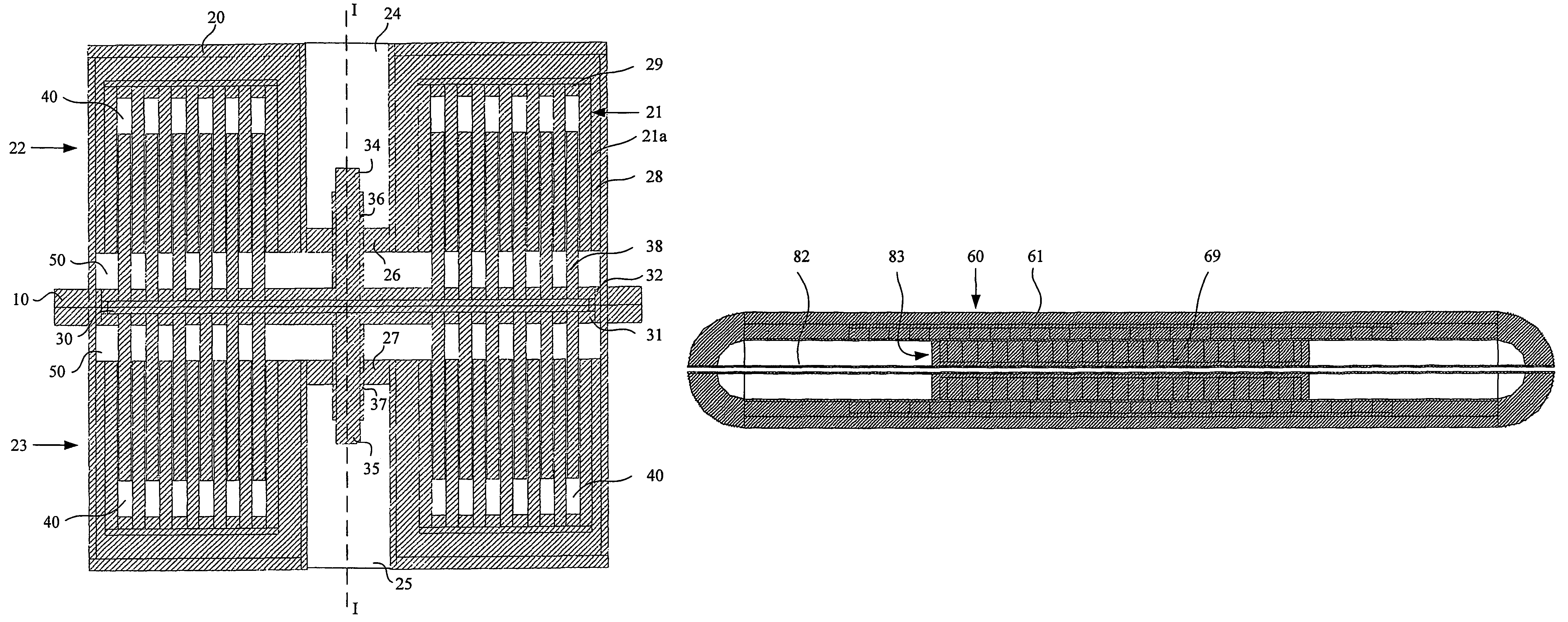
[0035]FIG. 1 shows a cross-section of a machine according to the invention. The machine and its main parts are built up concentrically around the axis I-I. That means that the machine is circular, when seen from above. In the description, the words up, below, above, below, and the like, are meant to be helpful for the understanding of the respective Figures. However, it is evident that the machine will work in different positions.

[0036]The machine comprises a casing 20 with a piston 30 which is moving back and forth in the piston along the axis I-I. Further arranged in the casing 20 is an electric coil arrangement 21 with coils 21a.

[0037]The casing comprises an upper chamber 22 and a lower chamber 23, which extend along the greater part of the periphery of the casing. Next to the axis I-I the casing comprises an external upper cavity 24, and an external lower cavity 25. At the bottom 26, 27 of these cavities 24, 25 are placed openings, the purpose of which will be described below.

[...


PUM


Abstract

Machine with an electromechanical converter, where a linear movable piston (30) is placed in a tubular cylinder casing (20). The piston supports a row of centrally placed annular permanent magnets (38) which produce an electromagnetic field of force. This is effective towards a surrounding row of annular coils (21). Such a machine can be driven as a motor or as a generator with a minimum of movable parts. At the ends of the closed cylinder is formed a chamber (40, 50), which forms a gas spring. In its simplest form the machine acts as a vibrator or as a vibration-driven generator. Additionally, to the gas springs, and at least at one end of the cylinder casing, can be placed a helical spring which ensures the central position of rest of the piston in the case of vertical installation. The piston can be connected to an axial bar (34) which is lead out of the machine on its one end for transmission of kinetic energy to or from the machine.

Description

[0001]This application is a filing under 35 USC 371 of PCT / NO2005 / 000035, filed Jan. 28, 2005.BACKGROUND OF THE INVENTION[0002]The present invention relates to a linear machine which includes an electromechanical converter with a linear movable piston which is arranged in a tubular cylinder. The invention also includes the use of this machine. In this application, primarily the disclosure is about use of the linear machine as an electrical motor, but it can also be relevant to make use of it as generator for the production of electrical energy.[0003]Known are different types of uses of such linear machines. Examples are compressors, vibrators, Stirling machines, motors, and generators.[0004]Such a linear machine comprises the following main parts: a piston, a coil arrangement, and a casing. The piston is magnetized, for example, with the aid of permanent magnets, which can be called an “armature” or “rotor”.[0005]The alternating current in the coil will result in setting up a varyin...

Claims


Application Information

Patent Timeline
Patent Type & Authority Patents(United States)
IPC IPC(8): H02K41/00F04B35/04H02K33/00H02K33/16H02K35/02
CPCF04B35/045H02K33/16H02K35/02
Inventor BRENNVALL, JON ERIKNILSSEN, ROBERT
Owner RESONATOR
Why Eureka
Try Eureka