System and method for therapy and diagnosis comprising translatory distributor for distribution of radiation

a translator and distributor technology, applied in the field of system and method for tumour therapy and diagnosis, can solve the problems of high percentage of deaths in western countries, limited penetration of activating radiation in the tissue of the activated tissue, and high cost of radiation therapy, so as to reduce the overall size of such a distributor, improve the switching function, and reduce the loss of diagnostic ligh

Active Publication Date: 2011-08-02
SPECTRACURE
View PDF11 Cites 7 Cited by
  • Summary
  • Abstract
  • Description
  • Claims
  • Application Information

AI Technical Summary

Benefits of technology

The present invention overcomes the above identified deficiencies in the art and solves at least the above identified problems by providing a system and a method according to the appended patent claims, wherein a very practical and efficient implementation of interactive IPDT is achieved in that different optical measurements for diagnostics and dosimetry can be performed in an integrated and simple way. An important application of the invention is interactive, interstitial photodynamic therapy, and / or interactive photothermal tumour therapy. According to the invention, the size of a system using existing optical radiation distributors, such as described in PCT / SE02 / 02050 is further reduced. Moreover, the invention allows such an existing optical radiation distributor to improve switching functionality with a reduced overall size of such a distributor. Losses for diagnostic light are reduced as at least one site of attenuation, i.e. one extra switch, is eliminated according to one embodiment of the invention. The invention offers also increased flexibility and reduces the influence of mechanical tolerances. Furthermore, the invention is an alternative solution to the problems and drawbacks associated with the systems according to the prior art.

Problems solved by technology

In spite of great progress within therapy, the tumour diseases continue to account for much human suffering, and are responsible for a high percentage of deaths in western countries.
Singlet oxygen is known to be particularly toxic to tissue; cells are eradicated and the tissue goes in necrosis.
The limited penetration in the tissue of the activating radiation is a big drawback of PDT.
However, such open beam paths result in a strongly lossy beamsplitting and the resulting losses of light drastically impair the light distribution as well as the light measurement.
Furthermore, such a system must often be adjusted optically, which is also an important drawback in connection with clinical treatments.
The system is also large and heavy and difficult to integrate into a user-friendly apparatus.
Moreover, it is difficult to control the power of the light sent into each individual fibre, which makes the measurement results unreliable.
However, when changing from one constellation to another, the flexible wire has to be retracted between each switching process, otherwise the relative movement of the switch element is obstructed.
Furthermore, the pipelines are not suitable for conducting radiation themselves, they just provide external protection and guidance to the flexible wires conveyed therein.
The construction is also bulky and not suited for small optical fibres.
Moreover, the arrangement of the disclosure is not suited for diagnosis, only for therapy, and no interactive co-operation is disclosed.
However, only the use of a single wavelength light source is disclosed, it is thus not possible to have multiple diagnostics performed without manually exchanging the light source.
Moreover, it is not possible to switch between different constellations of the light fibres, i.e. all fibres always have the same function (light in or light out).
This solution offers for instance no neither interactive treatment nor mapping of tumours.

Method used


Image

  • System and method for therapy and diagnosis comprising translatory distributor for distribution of radiation
  • System and method for therapy and diagnosis comprising translatory distributor for distribution of radiation
  • System and method for therapy and diagnosis comprising translatory distributor for distribution of radiation

Examples


Embodiment Construction

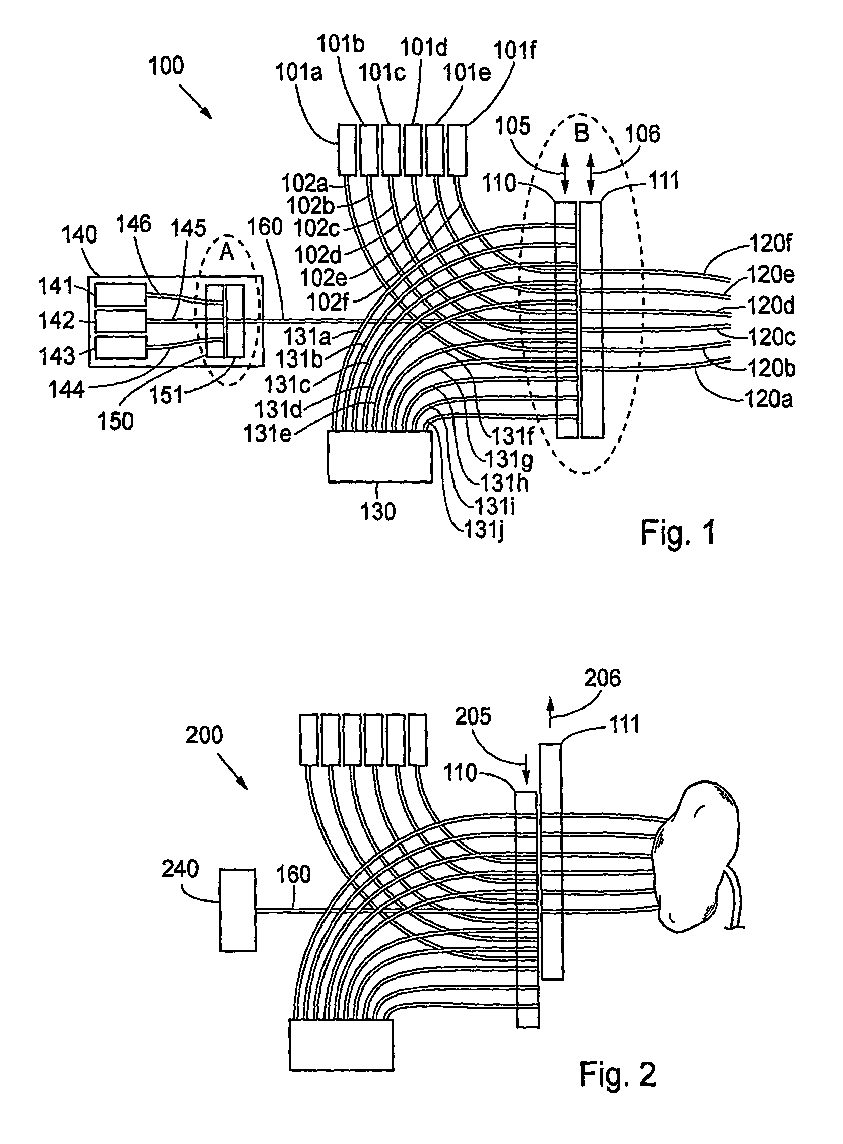
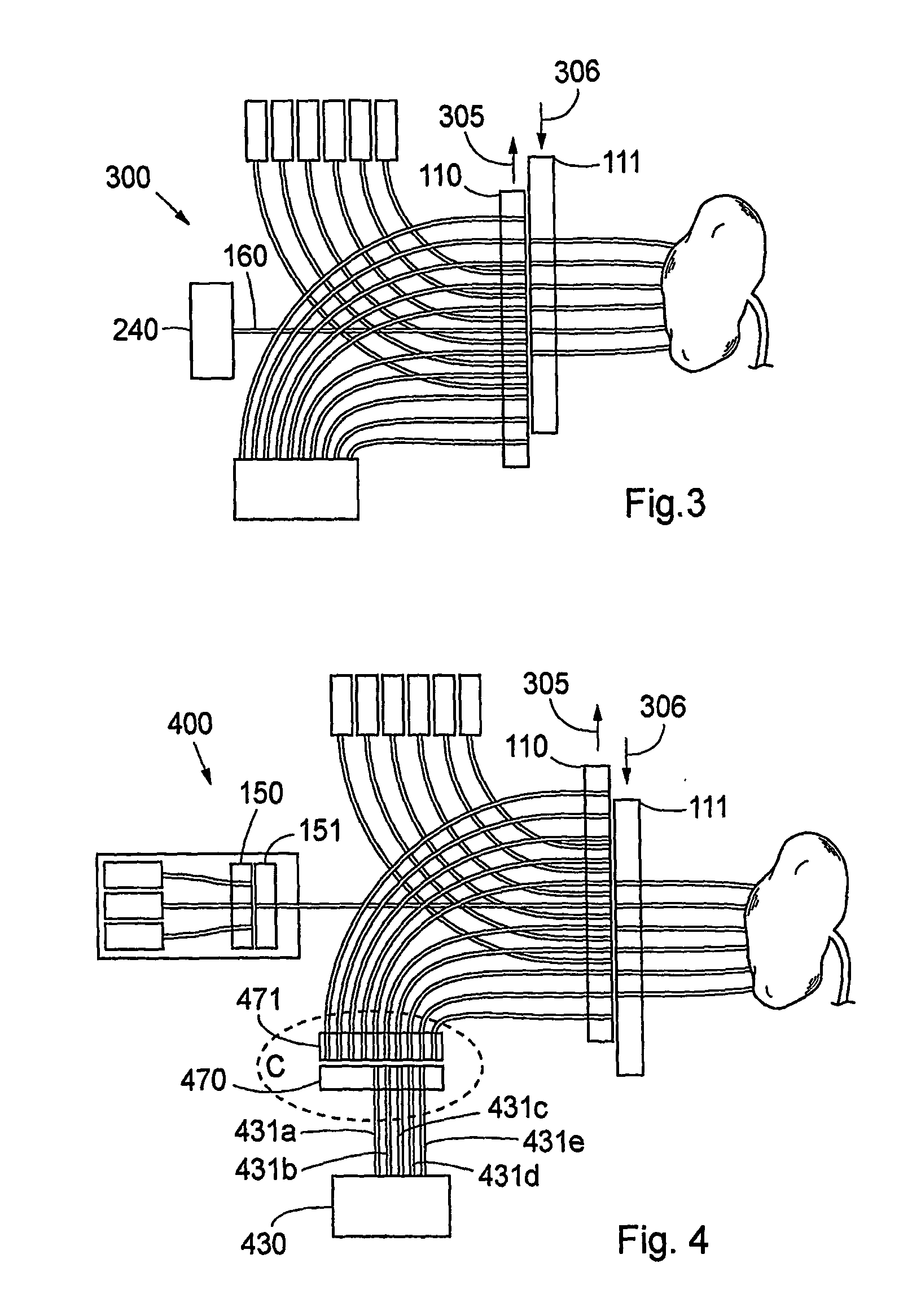
FIG. 1 is a schematic view illustrating an embodiment of the invention in a system according to the invention. In order to simplify the description of the embodiments, reference numerals for similar elements shown in the figures are not repeated in all figures. An embodiment 100 of the distributor of the system according to the invention is now described with reference to FIGS. 1-4 and FIG. 9. A distributor 1 for radiation comprises two substantially in close proximity to each other lying longitudinal longitudinal translatory elements made of, e.g. 1 cm thick steel or a some mm thick composite material, depending on different parameters, such as the way of fastening the radiation conductors to the translatory elements. When a contact element, such as conventional optical fibre couplings are used for fixing the radiation conductors to the longitudinal translatory elements, these couplings ensure the mechanical stability and define the size of the elements. In case the radiation condu...


PUM


Abstract

A system and method for interactive interstitial photo-dynamic tumour therapy and / or photothermal tumour therapy of a human or animal, said system comprising at least one radiation distributor, which is arranged for distribution of optical radiation from at least one radiation source to a reaction site, or from the reaction site to at least one radiation sensor. The radiation distributor comprises at least one translatory displacement element being translatory movable relatively to another element. First ends of first radiation conductors are fixed to the first translatory displacement element and first ends of second radiation conductors are fixed to the other element, wherein the first and the second radiation conductors are connectable to each other in different constellations through translatory movement of the translatory displacement element and the other element relative each other in order to obtain different operation modes of said system.

Description

FIELD OF THE INVENTIONThe invention relates generally to a system and a method for therapy and diagnosis in a subject. More particularly, the system and method relate to a system and method for tumour therapy and diagnosis in a human or animal. Even more particularly, the invention relates to a system and method for preferably interactive photodynamic therapy (PDT) and / or photothermal therapy (PTT) and / or photodynamic diagnosis (PDD) of a site on and / or in a human or animal, wherein electromagnetic non-ionising radiation is conducted to the site for reaction with the radiation, wherein the system comprises a distributor of radiation from at least one source of radiation to a reaction site, and from the reaction site to at least one radiation sensor, respectively, and wherein the reaction site preferably is a tumour site with a tumour, such as a malignant tumour.BACKGROUND OF THE INVENTIONWithin the field of medical therapy of tumour diseases, a plurality of treatment modalities has ...

Claims


Application Information

Patent Timeline
Patent Type & Authority Patents(United States)
IPC IPC(8): A61N5/06A61BA61B5/00A61B17/00A61B18/20A61B18/22A61N5/01
CPCA61B5/0071A61B5/0084A61B5/0086A61N5/0601A61N5/062A61B5/0073A61B5/0075A61B2017/00057A61B2018/208A61N2005/0612A61N2005/0629
Inventor JOHANSSON, THOMASEKER, CHARLOTTAMALMBORG, JORGENMOGENSEN, LASSE WESSELTOFTSVANBERG, SUNETHOMPSON, MARCELO SOTOENGELS, STEFAN ANDERSSON
Owner SPECTRACURE
Why Eureka
Try Eureka