Acoustic leak detector with noise cancellation

a leak detector and noise cancellation technology, applied in the field of leak detectors, can solve the problem of low nose level, and achieve the effect of accurate detection of occurren

Active Publication Date: 2012-01-17
FUJI TECOM INC
View PDF13 Cites 2 Cited by
  • Summary
  • Abstract
  • Description
  • Claims
  • Application Information

AI Technical Summary

Benefits of technology

[0011]The present invention was made in the light of the circumstances as described above, and an object of the present invention is to provide a leakage detector capable of accurately detecting occurrence and a position of leakage in a buried fluid pipe line without fail even at night when the traffic noises by cars, pedestrians, and the like are temporally generated and also dairy life noises by in-store equipment installed in store staying open until late at night and automatic vending machines are constantly generated.
[0012]Another object of the present invention is to provide a leakage detector enabling even those not so skilled in the leakage detection work to accurately detect occurrence and a position of leakage in a buried fluid pipe line without fail.
[0014]With the configuration as described above, an optimal noise remover can be selected by taking into consideration the noises being generated in an environment where leakage detection is to be performed, and therefore it is possible to accurately detect occurrence and a position of leakage in a buried fluid pipe line without fail.
[0017]With the configuration as described above, a level of detected vibrations is provided not only as audio data, but also as visual data such as displays of numerical values or a graph, and therefore even those not so much skilled in the leakage detection work can accurately detect occurrence and a position of leakage in a buried fluid pipe line without fail.

Problems solved by technology

Even at night, however, actually the traffic noises by cars, pedestrians, and the like are temporally generated, and also dairy life noises by in-store equipment installed in store staying open until late at night and automatic vending machines are constantly generated, although the nose level is low.

Method used


Image

  • Acoustic leak detector with noise cancellation
  • Acoustic leak detector with noise cancellation
  • Acoustic leak detector with noise cancellation

Examples


Embodiment Construction

[0027]Preferred embodiments of a leakage detector according to the present invention are described in detail below with reference to the related drawings.

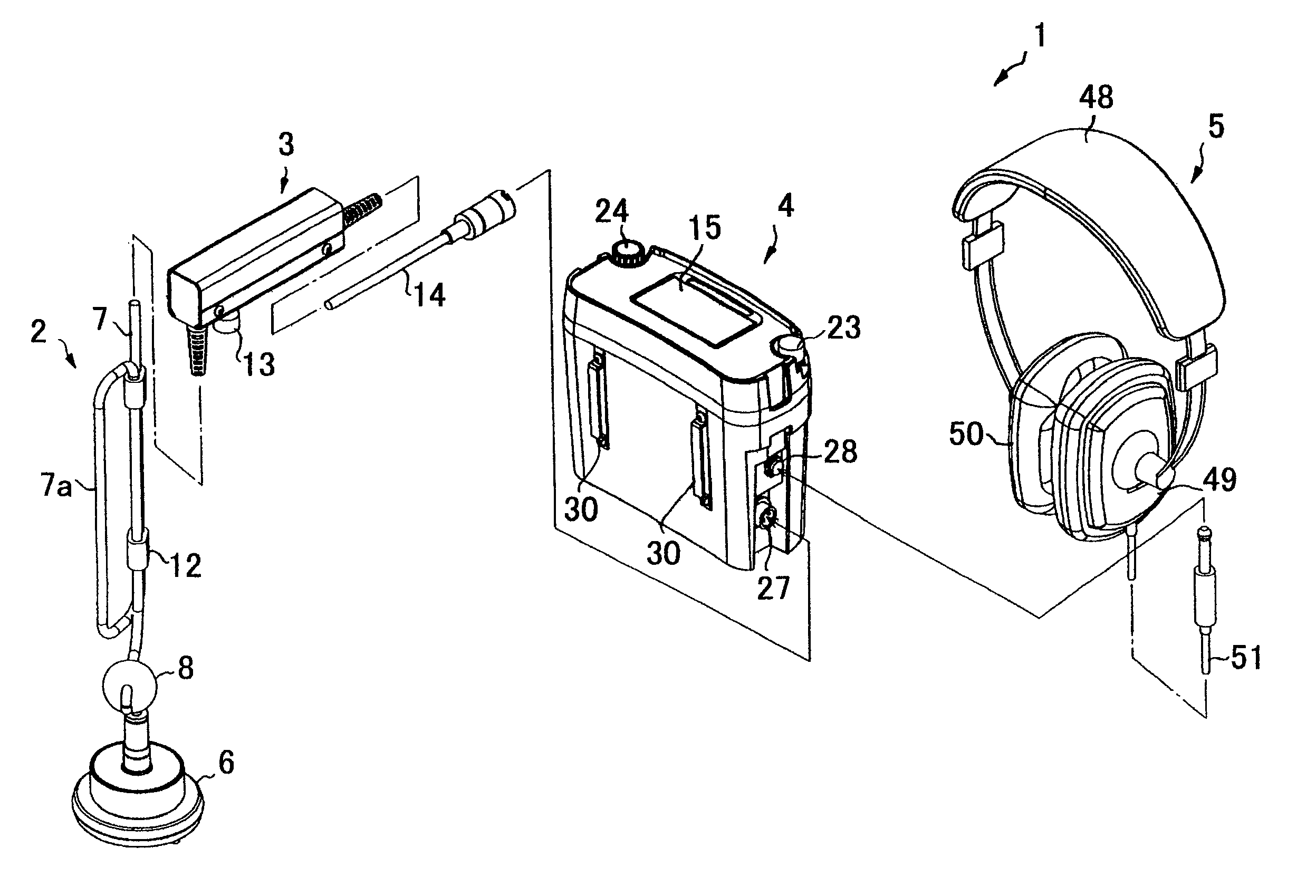
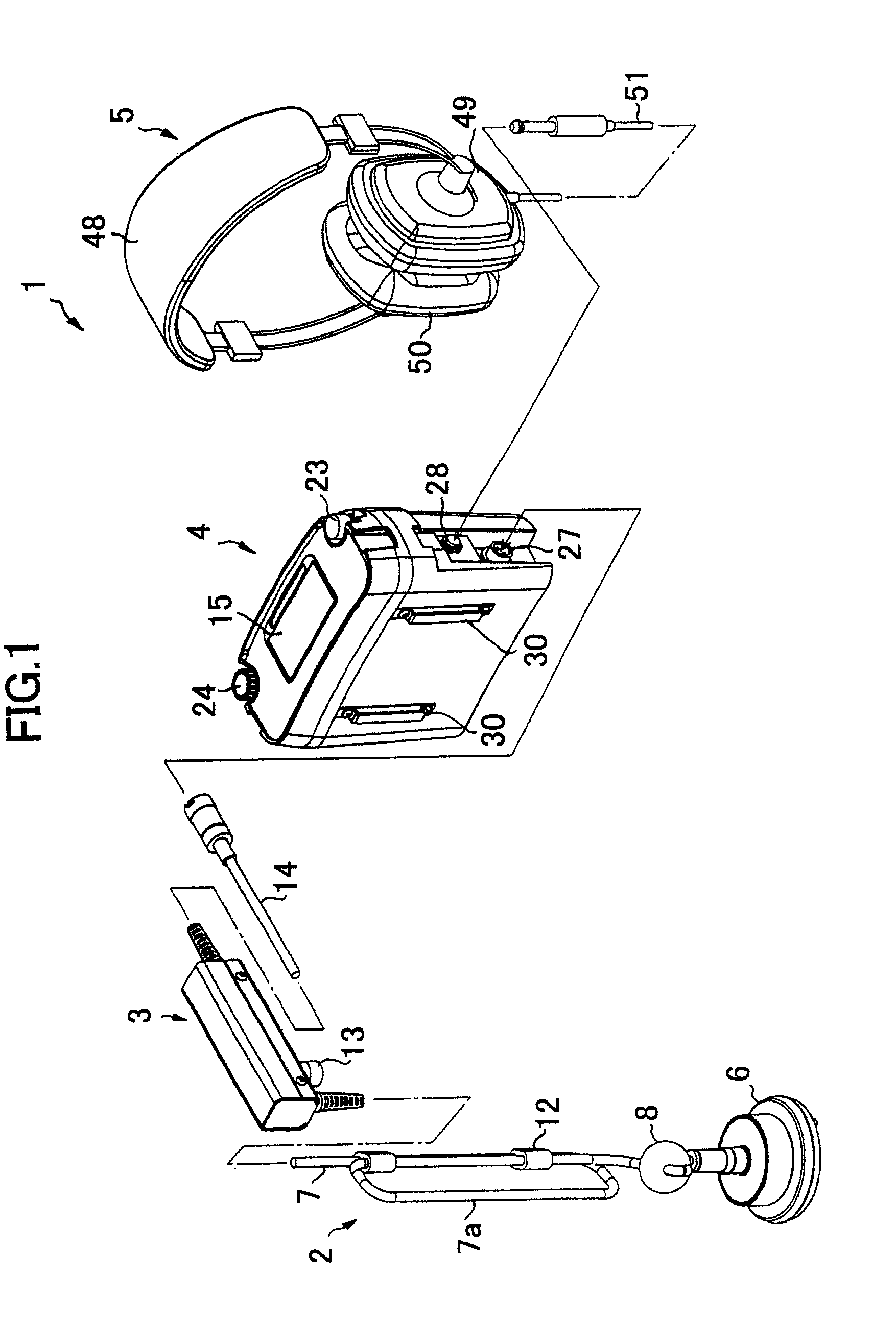
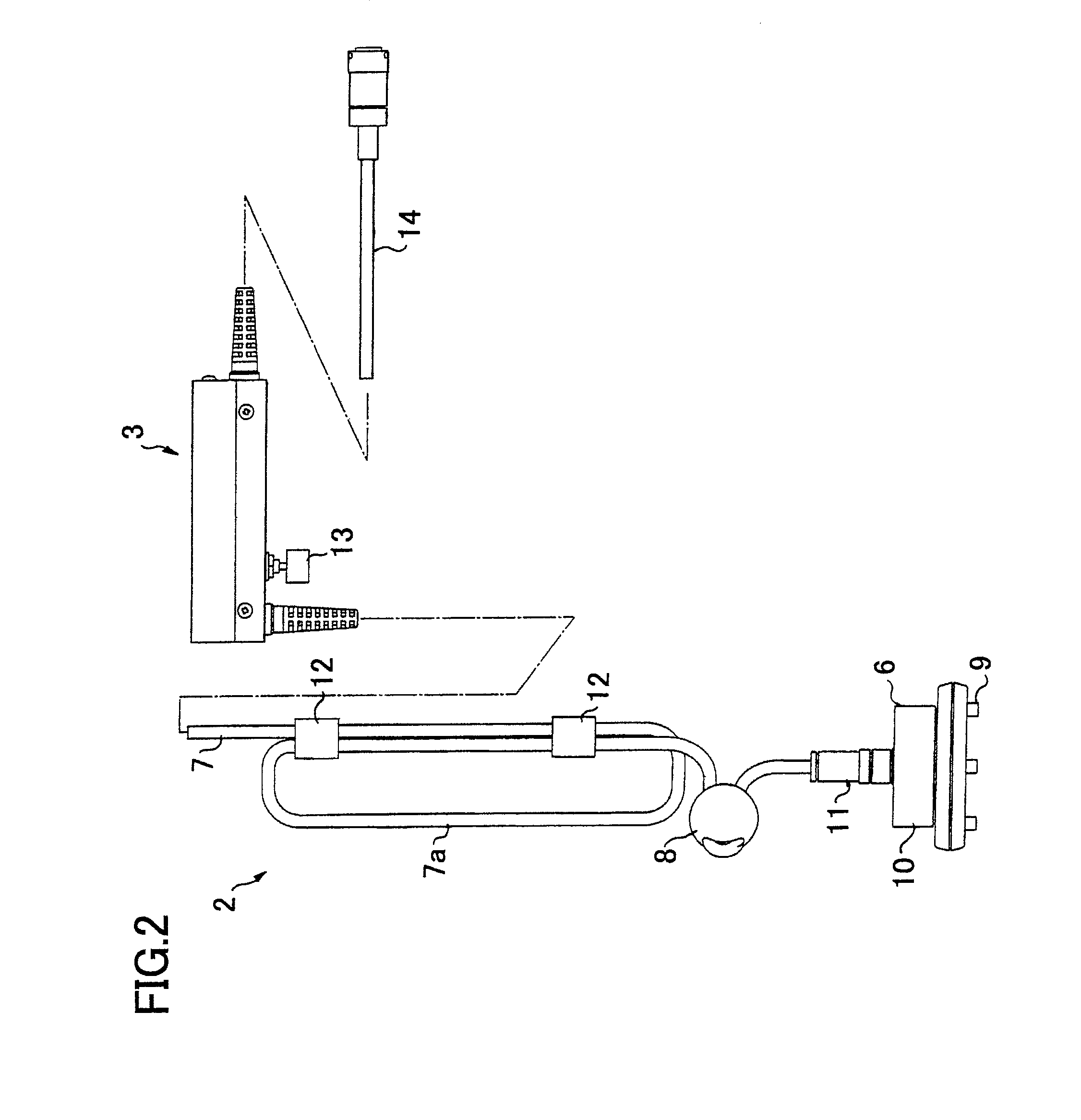
[0028]FIG. 1 is a perspective view illustrating a configuration of the leakage detector according to the present invention; FIG. 2 is a front view illustrating a vibration detector and a handle member; FIG. 3 is a cross-sectional view illustrating a noise absorbing member; FIG. 4 is a view illustrating a main body of the leakage detector, and FIG. 4A is a front view, FIG. 4B is a left side view, FIG. 4C is a top view, and FIG. 4D is a right side view each illustrating the main body of the leakage detector.

[0029]A leakage detector 1 according to the present invention comprises a vibration detector 2, a handle member 3, a main body of the detector 4, and a headphone 5, as shown in FIG. 1.

[0030]The vibration detector 2 comprises a pickup 6, a cord 7, and a noise absorbing member 8, as shown in FIG. 1 and FIG. 2.

[0031]The pickup 6, as ...


PUM


Abstract

The present invention provides a leakage detector enabling accurate and stable detection for occurrence and a position of leakage in a buried fluid pipe line and also making it possible for even those not so skilled in the leakage detection work to use the detector. The leakage detector 1 according to the present invention comprises a vibration detector 2 having a pickup 6 incorporating a piezoelectric element; a main body 4 of the detector incorporating voltage amplifiers 31, 37 for voltage-amplifying an output signal and a plurality types of noise removing units 33, 34, 35 for removing noises from the output signal, and a headphone 5. The main body 4 of the detector has a display unit 15 for displaying data for detected vibration sounds on a predefined screen.

Description

BACKGROUND OF THE INVENTION[0001]1. Field of the Invention[0002]The present invention relates to a leakage detector for detecting occurrence and positions of leakage of a fluid such as water or gas flowing a fluid conduit such as a water pipe or a gas pipe buried under the ground.[0003]2. Description of Related Art[0004]As a detector for detecting occurrence and positions of leakage of a fluid such as water or gas flowing a fluid conduit such as a water pipe line or a gas pipe line buried under the ground, there has been known an audible leakage detector 81 comprising a vibration detector 82 having a pickup 83 and a cord 84, a voltage amplifier 85, and a headphone 86 as shown in FIG. 8 (Refer to, for instance, Japanese Patent Laid-Open Publication No. HEI 10-325778).[0005]When occurrence and a position of leakage of water in a water pipe line is detected with the leakage detector 81, an operator holds the voltage amplifier 85 hung down from the operator's neck portion with a belt on...

Claims


Application Information

Patent Timeline
Patent Type & Authority Patents(United States)
IPC IPC(8): H04B15/00G01M3/18
CPCG01M3/243F17D5/06G01H11/08G01N29/36G01V1/001
Inventor KAJI, KATSUHIROSAIJO, KAZUHIRO
Owner FUJI TECOM INC
Why Eureka
Try Eureka