Detecting amplifier out-of-range conditions

a technology of amplifiers and out-of-range conditions, applied in the direction of electric devices, instruments, transportation and packaging, etc., to achieve the effect of widening the useful operating range, accurately detecting the occurrence of steps, and extending the useful operating rang

a technology of amplifiers and out-of-range conditions, applied in the direction of electric devices, instruments, transportation and packaging, etc., to achieve the effect of widening the useful operating range, accurately detecting the occurrence of steps, and extending the useful operating rang

US7427898B2Active Publication Date: 2008-09-23TEXAS INSTR INC

Image

  • Detecting amplifier out-of-range conditions
  • Detecting amplifier out-of-range conditions
  • Detecting amplifier out-of-range conditions

Examples


Embodiment Construction

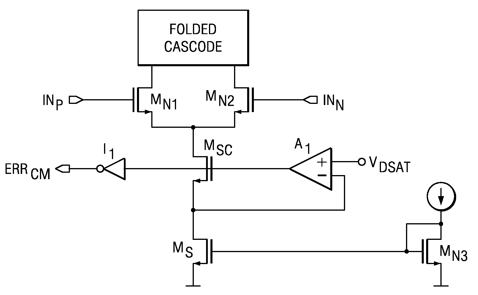
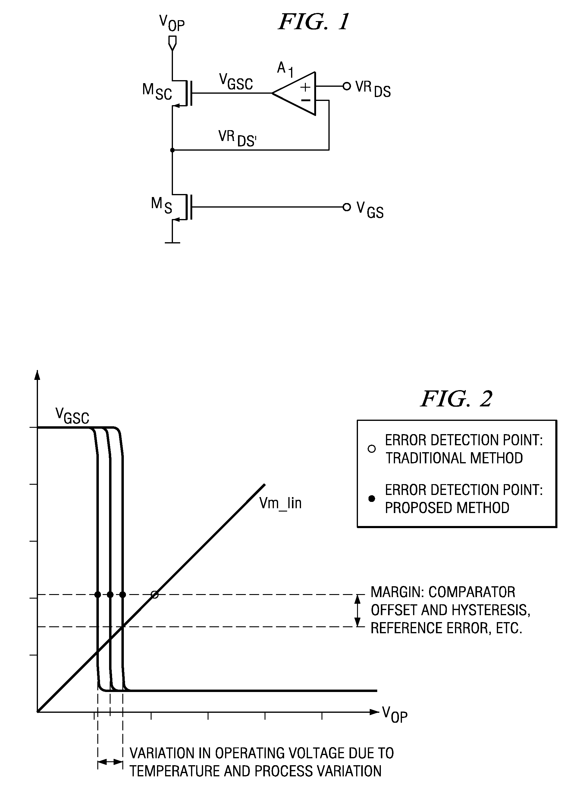
[0012]The impedance enhancement circuit in FIG. 1 is intended to maintain critical transistors in their optimally biased condition over various operating conditions (temperature, process variation, input and output voltage ranges, current range, etc.) and to improve the output impedance of current mirrors. The CMOS or BiCMOS circuit includes an n-channel control transistor MS connected in series with an n-channel cascode transistor MSC, and a differential amplifier A1. The differential amplifier A1 has an inverting input connected to the node between the control transistor and the cascode transistor, a non-inverting input connected to a reference voltage source VRDS and an output connected to the gate of the cascode transistor MSC. A control voltage VGS is applied to the gate of control transistor MS and the drain of cascode transistor MSC sinks an output current IOUT. A similar structure can be built with p-channel transistors, as current source rather than current sink.

[0013]The c...


PUM


Abstract

Out-of-range conditions are detected in amplifier CMOS or BiCMOS circuitry that includes a control transistor (MS) connected in series with a cascode transistor (MSC), and a differential amplifier (A1) with an inverting input connected to the node between the control transistor and the cascode transistor, a non-inverting input connected to a reference voltage source (VRDS) and an output connected to the gate of the cascode transistor (MSC). The voltage at the output of the differential amplifier (A1) is monitored, and an error condition is determined when the voltage exceeds or drops below a predetermined threshold value. The invention considerably widens the useful operating range, without requiring sophisticated or complex detection circuitry.

Description

CROSS-REFERENCE TO RELATED APPLICATIONS[0001]This application claims priority of German Patent Application Serial No. 10 2005 037 013.6, filed Aug. 5, 2005.TECHNICAL FIELD[0002]The invention relates to a method of detecting amplifier out-of-range conditions and to an amplifier with CMOS or BiCMOS amplifier circuitry.BACKGROUND[0003]Out-of-range conditions of an amplifier typically occur when the amplifier's inputs are outside of the common mode input range or when the output voltage of the amplifier gets too close to the voltage level of either supply rail due to a load error or an overdrive condition. Depending on the particular application, an error indication is needed to signal such an out-of-range condition.[0004]Traditionally, analog amplifiers have no detection and indication mechanism for out-of-range conditions. At best, a conventional method of detecting an out-of-range condition is to employ comparators that monitor the amplifier's input and / or output voltages and trip at...

Claims


Application Information

Patent Timeline
23 Sep 2008
Publication
US7427898B2
IPC
H03F3/04
CPC
H03F3/303; H03F3/45183; H03F2203/45484; H03F2203/45478
Inventors
SCHAFFER, VIOLA; IVANOV, MIKHAIL