Panelization method and system

a prefabricated plank and panel technology, applied in the field of prefabricated system, can solve problems such as limiting the space for mechanical openings, and achieve the effects of limiting space, reducing cost, and reducing construction costs

Active Publication Date: 2012-06-26
NEW MILLENNIUM BUILDING SYST +1
View PDF56 Cites 1 Cited by
  • Summary
  • Abstract
  • Description
  • Claims
  • Application Information

AI Technical Summary

Benefits of technology

[0012]A feature of the present invention is the use of a framing system that employs the use of beam elements that are connected to vertical columns. Traditional framing systems use I-beams that span between the centerline of vertical columns to provide support for floor components. These typical framing systems impede the space for mechanical openings between the columns. By using beam elements that are connected to either side of a four-sided column, a space is created between the beam elements at the centerline of the vertical columns. This space can then be used to create flexibility in design options. As an example, the space creates open areas through the floor system for mechanical equipment items such as piping, air supply ducts, and conduit.
[0013]Another feature of the present invention is the use of a spandrel beam that maintains the depth of the floor. In steel or concrete construction, the exterior beam that extends from column to column and marks the floor level between stories is commonly referred to as a spandrel beam. Spandrel beams are employed to support non-load bearing exterior fascia elements. Spandrel beams can also support floor loads; however, this application requires additional reinforcement. Traditionally, the challenge has been in providing reinforcement to the spandrel beam without increasing the depth of the slab, thus eliminating the need for a dropped beam, which is not aesthetically pleasing. The spandrel beam of the present invention is flush with the flooring of a building. Accordingly, the spandrel system accomplishes the challenging task of supporting an exterior curtain wall, while still providing an uninterrupted ceiling at the curtain wall.
[0014]Yet another feature of the present invention is the method for constructing a floor using the panelization system. Traditional methods for construction require that individual banded bundles of floor components be lifted onto horizontal beams. The bundles are then unbanded, and individual floor component pieces are distributed over the beams elements. The individual floor components are attached to the beam elements to complete the installation. This process becomes increasingly challenging, creating additional safety issues, thus adding expense to the construction of multi-story buildings. The present invention, however, provides for the positioning of a panelization system including preassembled floor components between the vertical columns at the desired floor elevations. Accordingly, the maneuvering and installation of individual floor components is avoided. The panelization system, when installed, gives construction workers immediate access to a large load supporting platform, thereby promoting construction safety.

Problems solved by technology

These typical framing systems impede the space for mechanical openings between the columns.

Method used


Image

  • Panelization method and system
  • Panelization method and system
  • Panelization method and system

Examples


Embodiment Construction

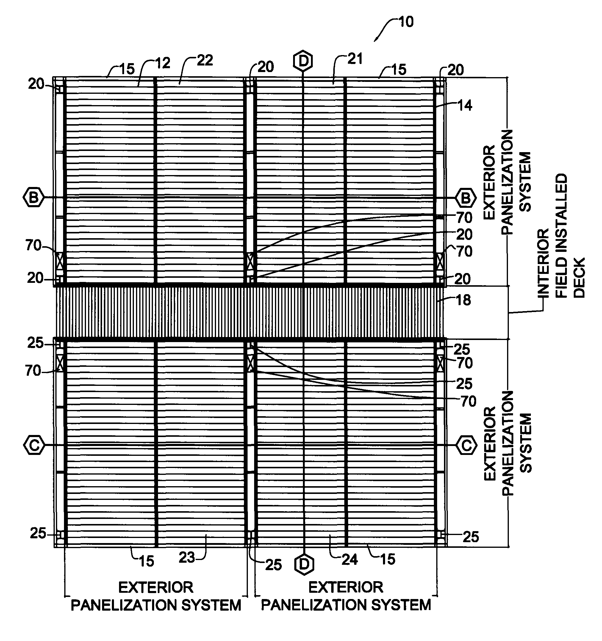
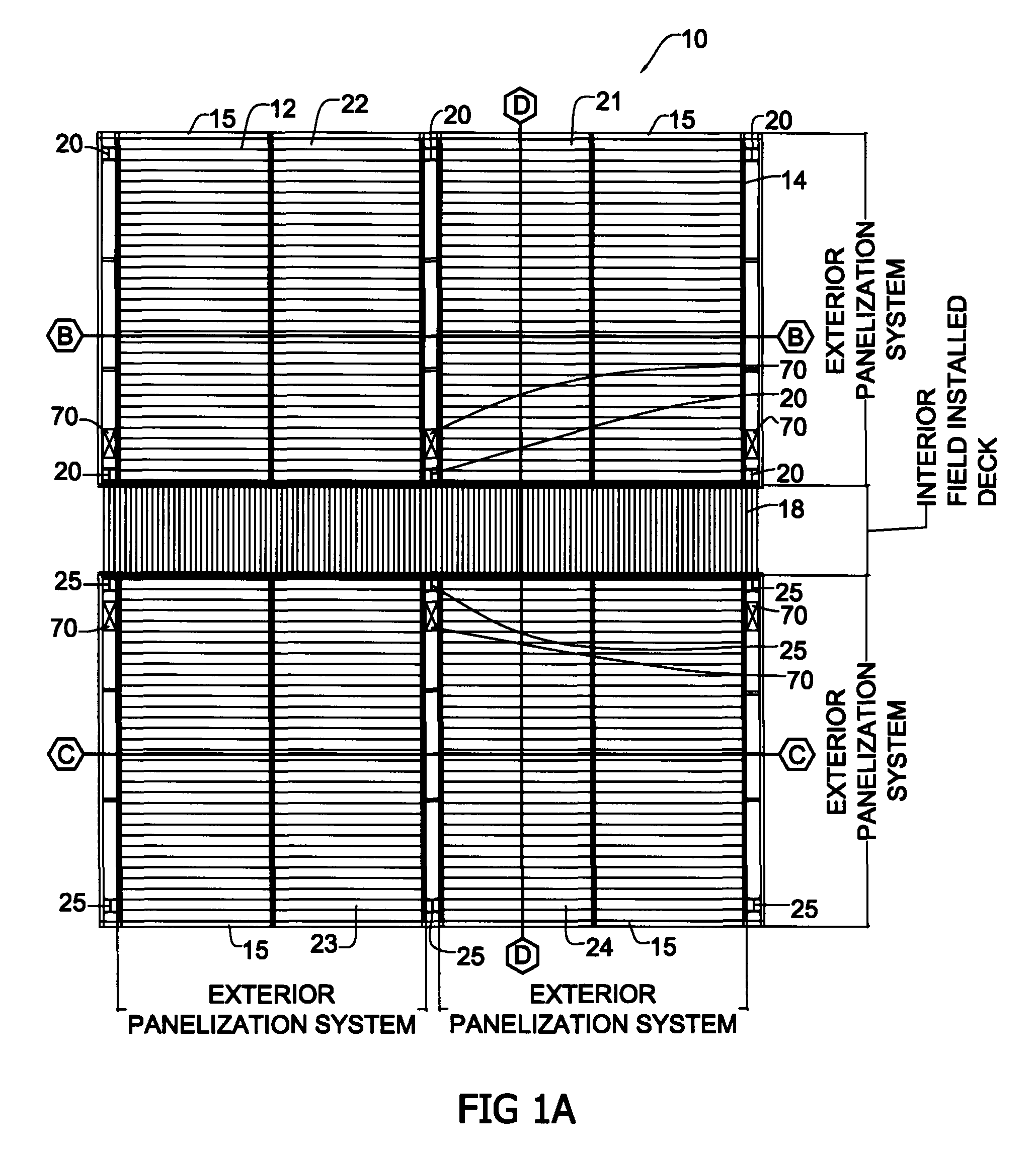
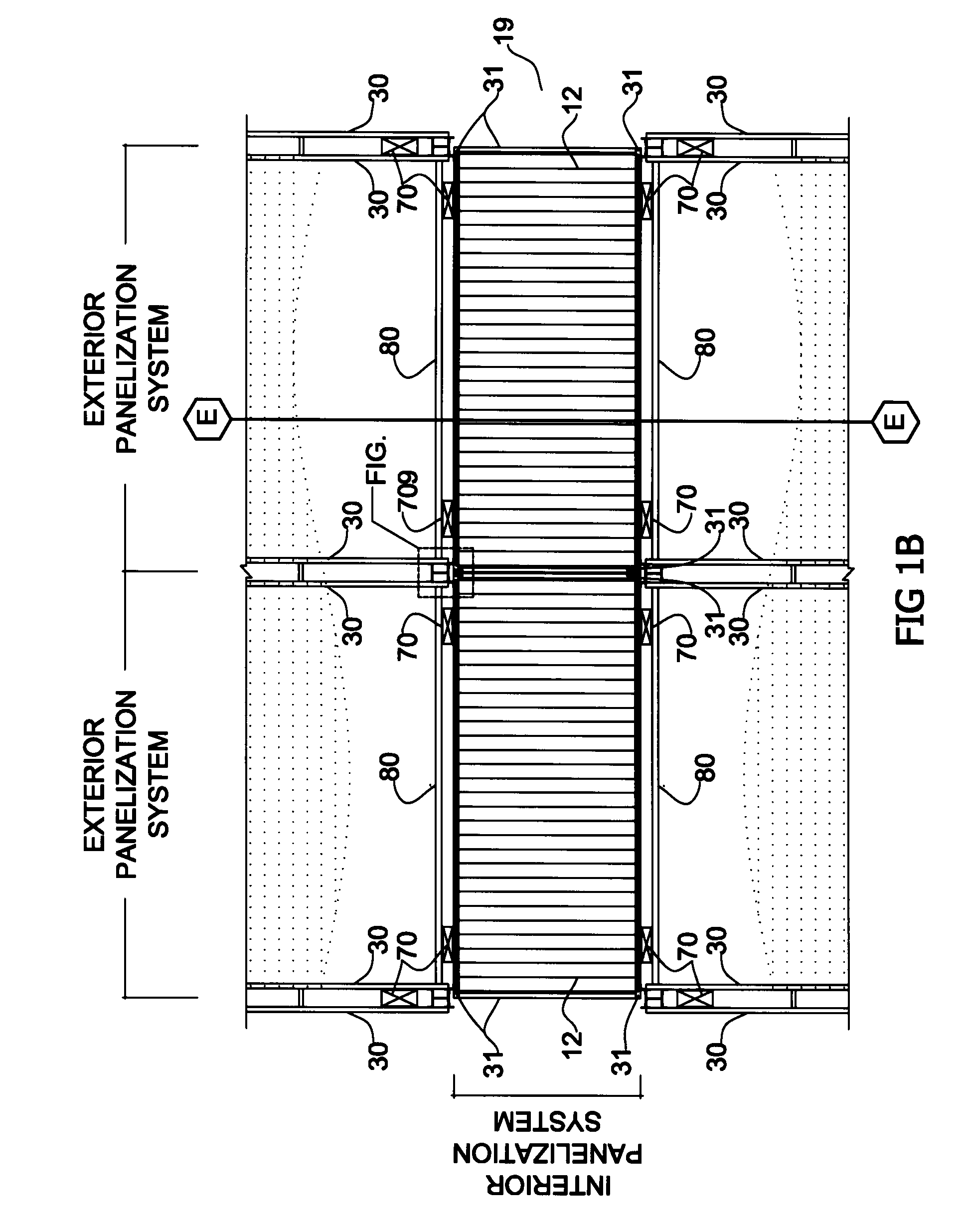
[0033]The present invention includes a panelization system and method. As illustrated in the drawings, and in particular FIG. 1A, a panelization system that is an exterior panelization system 10 includes a floor component 12 and a frame component 14. This panelization system 10 can be incorporated within a variety of conventional constructions, which include a variety of conventional construction components. By way of example and not limitation, the panelization system 10 of the present invention is shown as being incorporated into a building having a plurality of vertical columns 20 and 25 that form the perimeters of a first, second, third and fourth zone 21, 22, 23, 24. As illustrated, the first and second zones 21, 22 share vertical columns 20, and the third and fourth zone 23, 24 share vertical columns 25. Additionally, the first and second zones 21, 22 are separated from the third and fourth zones 23, 24 by a field installed partition component 18, such as a deck section that c...


PUM


Abstract

A prefabrication system having a floor component and a frame component. In particular, the floor component includes a deck member, which can be made of deck sections, profiles, or panels. For example, the deck member can be made of continuous panels that cover the desired width and length of the floor component. Alternatively, the deck member can be made of preassembled sections that are combined in juxtaposed relation to form the desired width and length. The frame component includes opposing horizontal support channels that are attached to opposing vertical columns, respectfully.

Description

CROSS REFERENCE TO RELATED APPLICATIONS[0001]Not applicable.STATEMENT REGARDING FEDERALLY SPONSORED RESEARCH OR DEVELOPMENT[0002]Not applicable.REFERENCE TO A SEQUENCE LISTING, A TABLE, OR A COMPUTER PROGRAM LISTING COMPACT DISC APPENDIX[0003]Not Applicable.BACKGROUND OF THE INVENTION[0004]The present invention relates generally to prefabrication systems, and, more particularly, to systems employing prefabricated planks and frames.[0005]A major concern in building construction is minimizing costs, maintaining a safe working environment and maximizing architectural flexibility and creativity. Striking this balance is the greatest challenge faced in developing prefabrication systems. Thus far, prefabrication systems have lacked in quality because of the need to reduce the costs of the materials employed, as costs for non-standard parts, as well as labor costs for the mounting and finishing steps, tend to be very high.[0006]Additionally, prior prefabrication systems require repetitive ...

Claims


Application Information

Patent Timeline
Patent Type & Authority Patents(United States)
IPC IPC(8): E04B1/00
CPCE04B5/19E04C3/293
Inventor WILLIAMS, MARTINLINDLEY, II, BILL R.MEYER, BRIAN JACOB
Owner NEW MILLENNIUM BUILDING SYST
Why Eureka
Try Eureka