Method and system for distinctively displaying selected floor with sufficient details in a three-dimensional building model

a three-dimensional building model and selected floor technology, applied in the field of data processing methods and systems, can solve problems such as difficulty in presenting interior details of a particular floor/level, common highlighting methods such as shading the flat plane of the selected floor or placing a wireframe around the selected floor, and suffer from disorientation

Active Publication Date: 2012-07-31
HONEYWELL INT INC
View PDF5 Cites 34 Cited by
  • Summary
  • Abstract
  • Description
  • Claims
  • Application Information

AI Technical Summary

Benefits of technology

[0008]It is another aspect of the present invention to provide for improved three-dimensional building models.
[0010]The aforementioned aspects and other objectives and advantages can now be achieved as described herein. A method and system for distinctively displaying building features with sufficient details in a three-dimensional building model is disclosed. One or more graphical metaphors can be provided, which permit a user to select with an enhanced granularity one or more building features from among a plurality of building features associated with a three-dimensional model of a building. Thereafter, one or more building features can be graphically selected by the user utilizing one or more such graphical metaphors, in response to a particular user input, thereby allowing the user the ability to clearly identify, graphically manipulate and distinguish building features among the building features to thereby correctly visualize the selected building feature with respect to the three-dimensional model of the building.

Problems solved by technology

Users of three-dimensional graphical models of buildings, however, sometimes suffer from disorientation as they view and manipulate three-dimensional building graphics.
Common highlighting methods such as shading the flat plane of the selected floor or placing a wireframe around the selected floor can be problematic, particularly if textures are used to render the walls of the building.
Also, it is difficult to present interior details of a particular floor / level such as walls and key objects with the selected floor highlighted, but not clearly separated from the floor above and below it.

Method used


Image

  • Method and system for distinctively displaying selected floor with sufficient details in a three-dimensional building model
  • Method and system for distinctively displaying selected floor with sufficient details in a three-dimensional building model
  • Method and system for distinctively displaying selected floor with sufficient details in a three-dimensional building model

Examples


Embodiment Construction

[0029]The particular values and configurations discussed in these non-limiting examples can be varied and are cited merely to illustrate at least one embodiment and are not intended to limit the scope thereof.

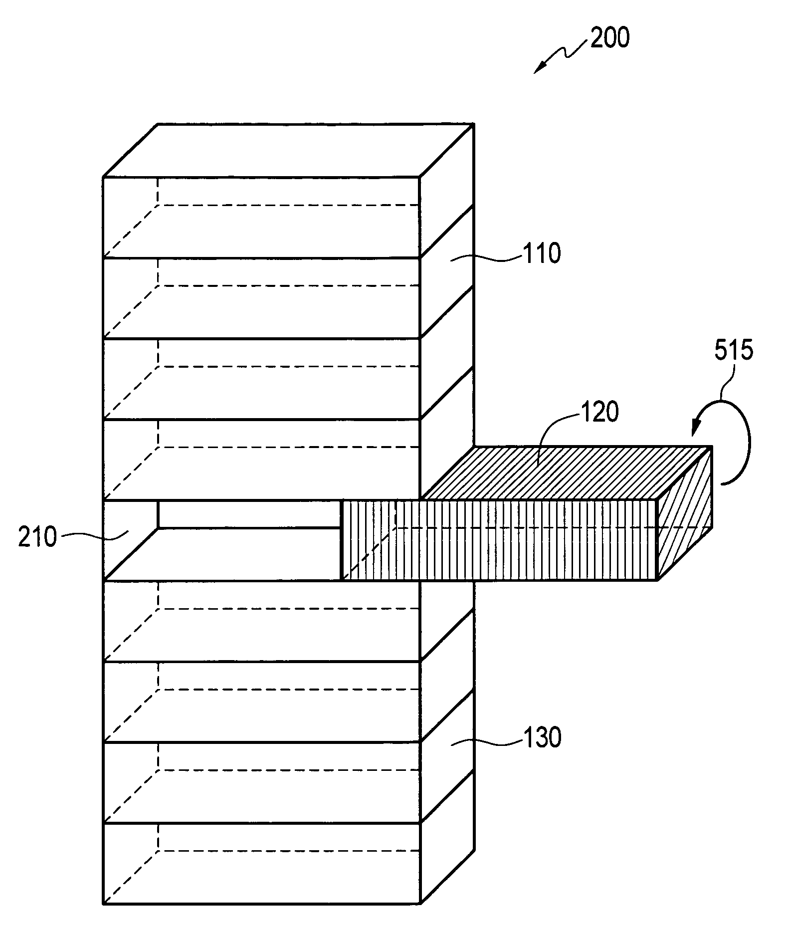
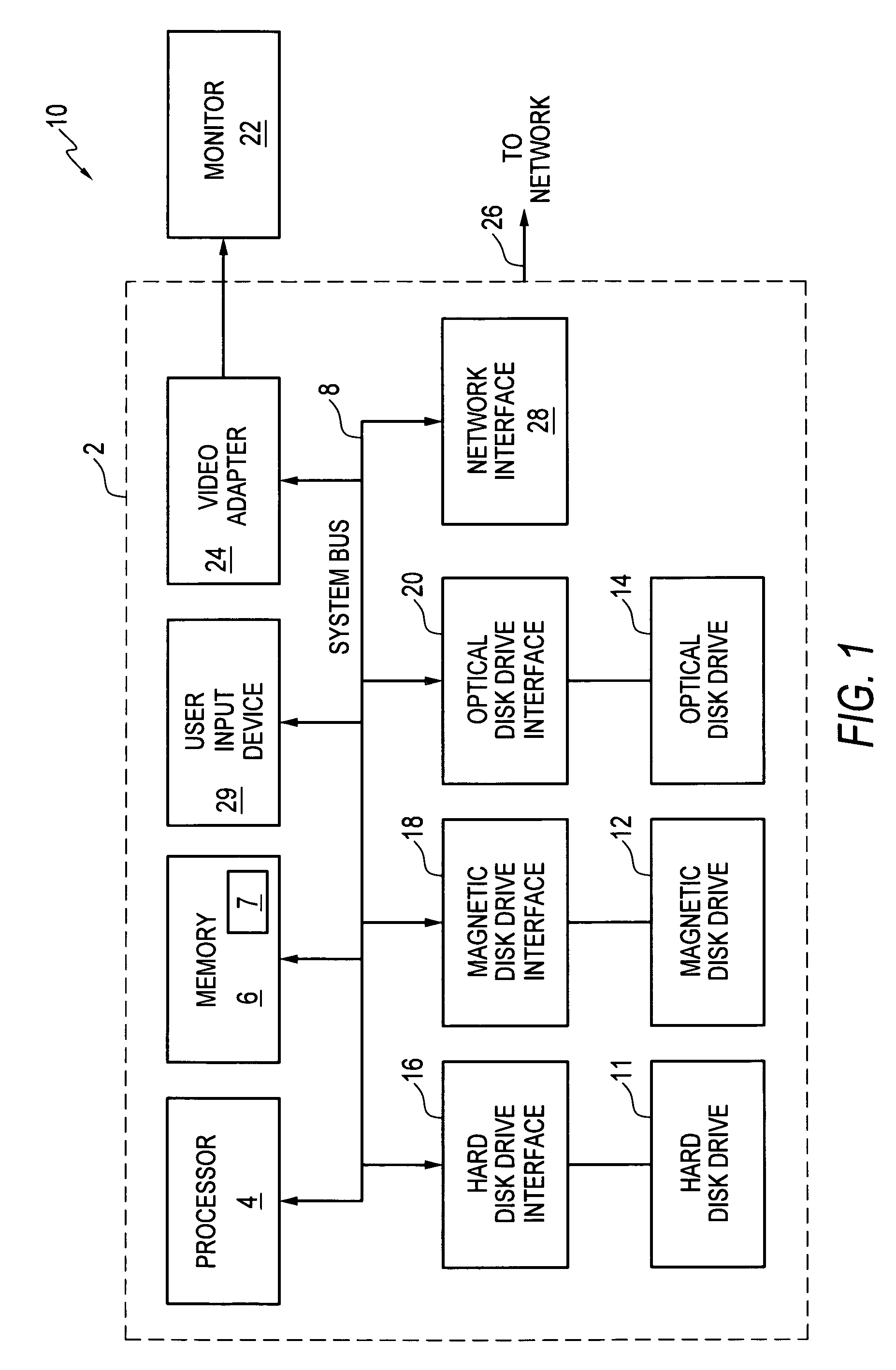
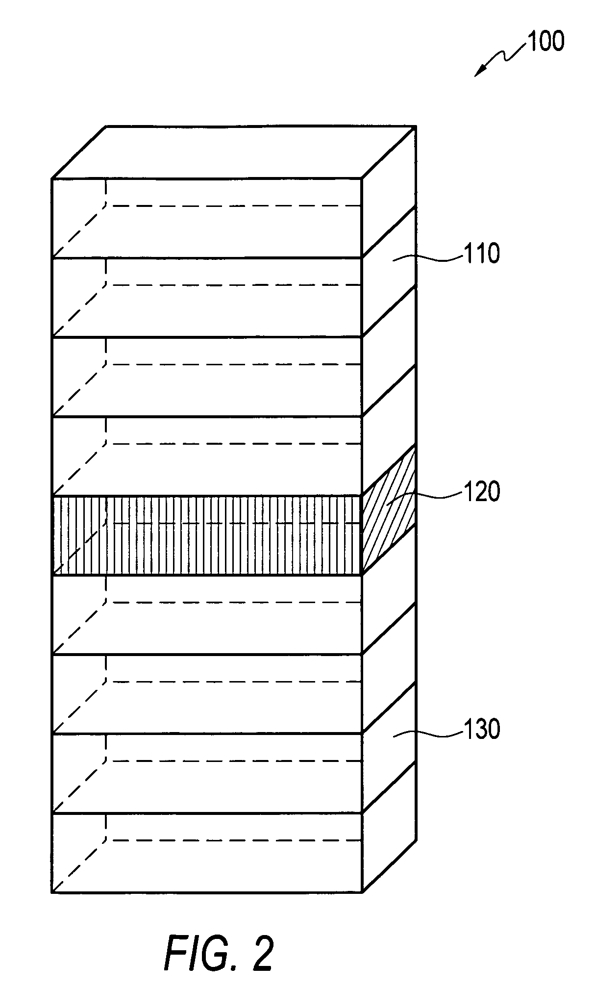
[0030]FIG. 1 illustrates a block diagram of a data-processing apparatus 10, which can be utilized to implement a preferred embodiment. Data-processing apparatus 10 can be used to implement a method for distinctively displaying selected building features (e.g., floors) with sufficient details in a three-dimensional building model as described in greater detail herein. Data-processing apparatus 10 can be configured to include a general purpose computing device, such as a computer 2. The computer 2 includes a processing unit 4, a memory 6, and a system bus 8 that operatively couples the various system components to the processing unit 4. One or more processing units 4 operate as either a single central processing unit (CPU) or a parallel processing environment. Data-processing app...


PUM


Abstract

A method, system and program product for distinctively displaying selected floors with sufficient details in a three-dimensional building model includes graphical metaphors that permit a selected or highlighted floor and their respective elements to be absolutely clear and distinct from the floors immediately above and below. The graphically displayed metaphors comprise “drawers”, “wireframe”, “expansion / compression”, “projected floor”, “sliding unselected floors”, “turning the pages”, “big map-small map”, and “fisheye” graphical configurations. Such graphically displayed metaphors can be utilized to highlight a selected floor, separate it from adjacent floors, and provide a graphical effect of depicting the floor's vertical position within a building.

Description

TECHNICAL FIELD[0001]Embodiments are generally related to data-processing methods and systems. Embodiments are additionally related to the computer-aided design of buildings. Embodiments are also related to three-dimensional building models, and techniques for distinctively displaying selected building floors with sufficient details in three-dimensional building models.BACKGROUND OF THE INVENTION[0002]Three-dimensional models of large buildings are used in graphical displays to support situation awareness in a variety of situations, such as, for example, firefighting, building security, and HVAC (Heating, Ventilating and Air conditioning) management. In a firefighting scenario, for example, a semitransparent three-dimensional model of a building would be helpful for providing a “birds-eye” perspective view of a building, along with a view from the outside looking in, and with respect to locations of activated smoke and heat detectors in three-dimensional space. From such a display, ...

Claims


Application Information

Patent Timeline
Patent Type & Authority Patents(United States)
IPC IPC(8): G09G5/00
CPCG06T19/20G06T2210/04G06T2219/2012G06T2219/2016G06T2219/2024
Inventor JIN, JANET JZXYAJUN, ZHANG ZYJPLOCHER, THOMAS A.ZHANG, RUICHEN, ENYI
Owner HONEYWELL INT INC
Why Eureka
Try Eureka