Tidal energy system

a technology of tidal energy and water supply, which is applied in the direction of sea energy generation, tide stream/damless hydropower, electrical equipment, etc., can solve the problem of achieve the effect of improving the free-stream tidal energy system and the greater damage to tidal energy equipment from storms

Inactive Publication Date: 2012-11-13
KINGSTON WILLIAM
View PDF6 Cites 9 Cited by
  • Summary
  • Abstract
  • Description
  • Claims
  • Application Information

AI Technical Summary

Benefits of technology

[0005]This invention overcomes these drawbacks. In addition, the danger of damage to tidal energy equipment from storms is greater the closer to the surface the equipment in positioned. But because the energy in a water wave is effectively attenuated to zero at half the wavelength, a free-stream tidal energy system can be improved by arranging for its reaction means to be positioned at different levels, according to the diurnal and lunar month variations in the rate of tidal flow and the presence of turbulence due to storms. This invention enables automatic optimum positioning of the reaction means for capturing the tidal energy, when the tide is running and when it is reversing direction, as well as when danger from storms is predicted.

Problems solved by technology

In addition, the danger of damage to tidal energy equipment from storms is greater the closer to the surface the equipment in positioned.

Method used


Image

  • Tidal energy system
  • Tidal energy system
  • Tidal energy system

Examples


Embodiment Construction

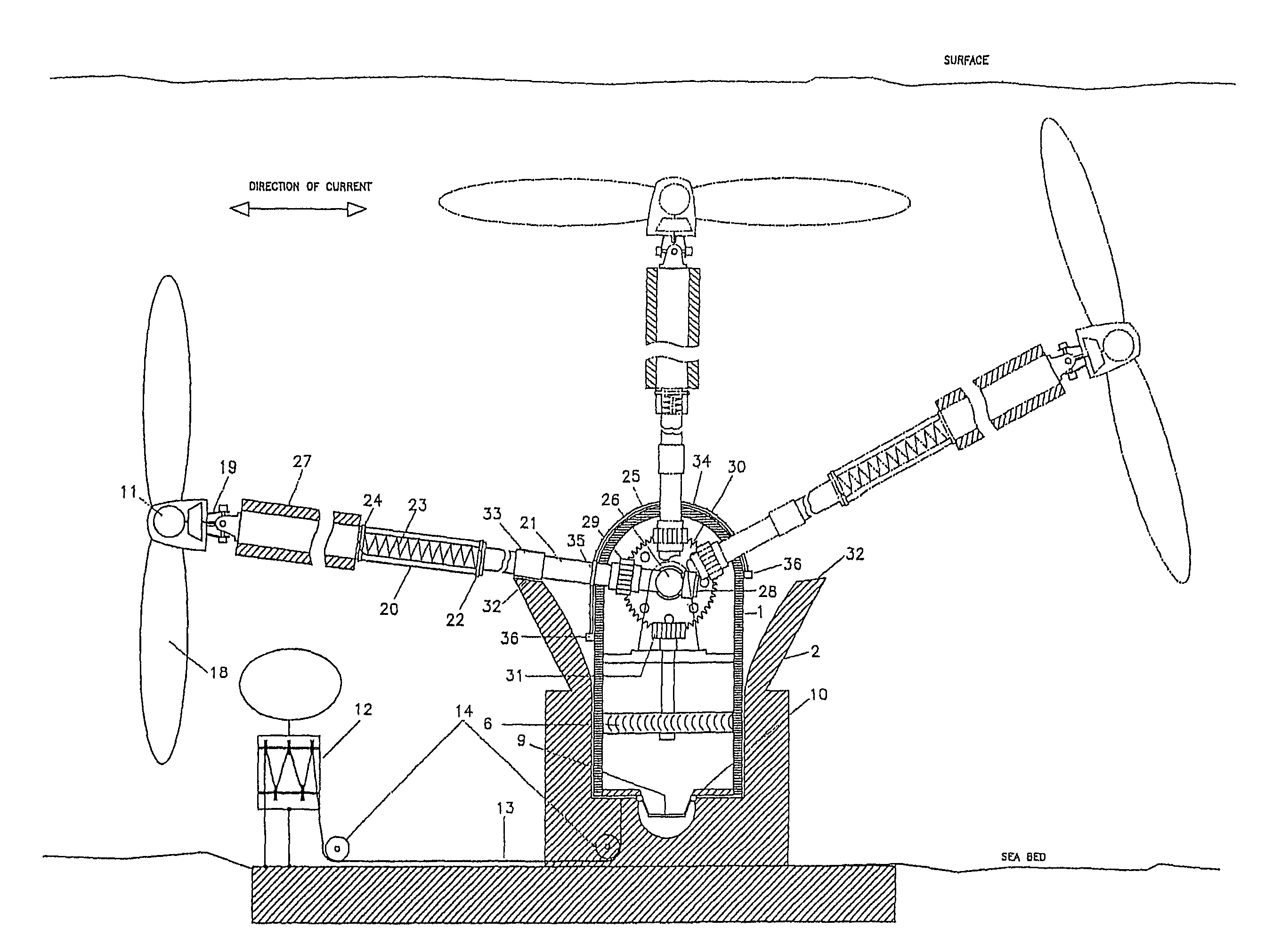
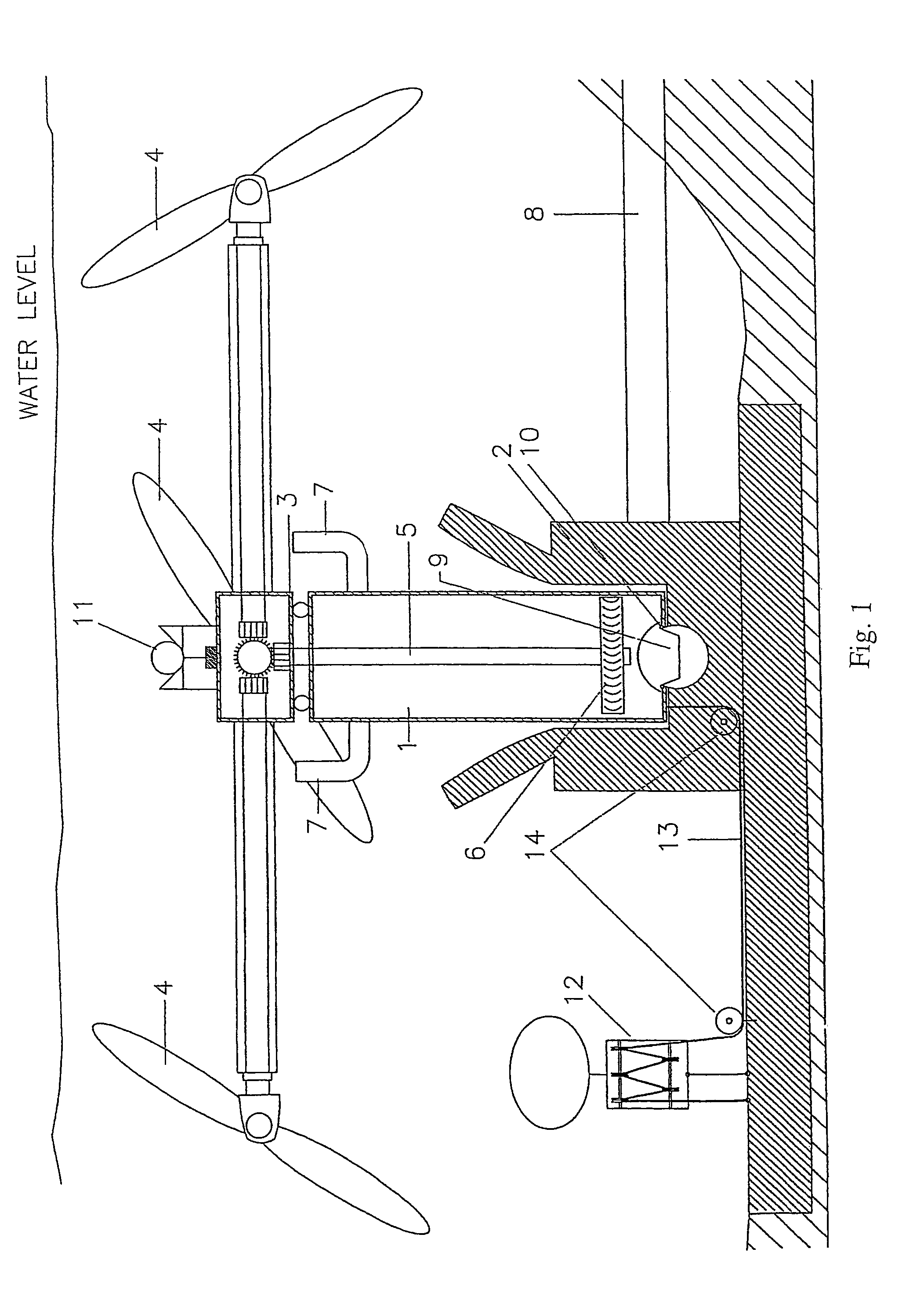
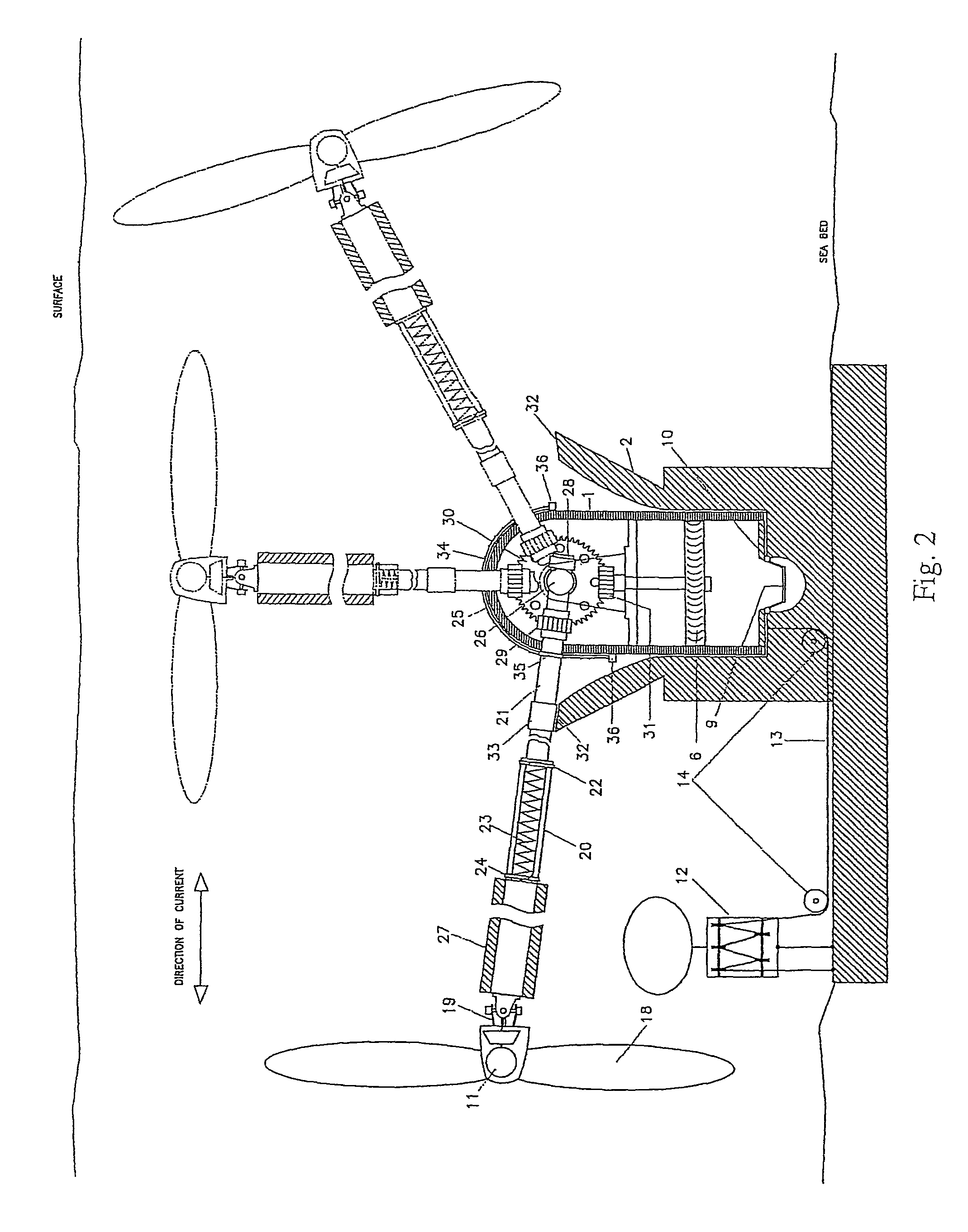
[0017]In FIG. 1, a substantially cylindrical housing for a water pump (1) is adapted to nest closely in the lower part of an anchor chamber which has a funnel-shaped open top (2) fixed to the sea bed. Gearbox (3) is rotatably fixed to the top of housing (1) and transmits power extracted from the tidal flow by reaction means on drive shafts (4, 4, 4) connected in gearbox (3) by a gear train and common drive shaft (5) to impeller (6). Gearbox (3) is rotatable so as to allow reaction means (4,4,4) to align themselves in accordance with reversal of the tidal stream's direction. To avoid carrying debris which is frequently in the water stream close to the sea bed, into the mechanism, water for pumping enters at the top of tubes (7, 7), whence it is forced by impeller (6) into pipeline (8) through port (9) in the centre of the underside of housing (1) and a corresponding opening in the top of pipeline (8). Sealing between these two components is then achieved through the pressure of the w...


PUM


Abstract

A tidal energy capture means connects a turbine to its anchor by telescopic members which pivot about the anchor as axis in the plane of the tidal flow and whose combined length depends upon the force of this flow. These members can be locked at prescribed lengths by a remote signal, to control the level of the turbine during this movement. The anchor consists of a plug and socket, with buoyancy means for positioning the plug in the socket, and the telescopic members can be a rotatable shaft which drives equipment in the plug.

Description

[0001]This is a continuation-in-part application, which claims priority from my application Ser. No. 12 / 087,756, filed Jul. 14, 2008 which will be expressly abandoned on the filing date of this application. Application Ser. No. 12 / 087,756 in turn is a 371 application from my PCT application No. WO2007IE00004.[0002]The new disclosure is in FIGS. 7-9 and the explanation thereof, and claims priority from application No. 1016714.6, filed in Great Britain on Oct. 4, 2010.TECHNICAL FIELD[0003]The technical field of this invention is that of capturing energy from the tides, especially by the ‘free-stream’ method which does not use a barrage.BACKGROUND ART[0004]Since the energy in a stream of water varies as the cube of its speed, it is desirable to locate ‘free-stream’ tidal energy devices where the stream is fastest. For example, headlands form obstacles to a tidal stream which cause the stream to accelerate as it passes around them. Also, because of boundary layer effects, more energy is...

Claims


Application Information

Patent Timeline
Patent Type & Authority Patents(United States)
IPC IPC(8): F03B13/00H02P9/04
CPCF03B13/264F05B2240/97Y02E10/38Y02E10/28Y02E10/30Y02E10/20
Inventor KINGSTON, WILLIAM
Owner KINGSTON WILLIAM
Why Eureka
Try Eureka