
Method And Apparatus For Controlling Buffer Overflow In A Communication System

a communication system and buffer control technology, applied in broadcast system types, digital audio broadcasting, digital transmission, etc., can solve problems such as more annoying perception, and achieve the effects of reducing the danger of further buffer overflow within a short period of time, preventing buffer overflow, and quickly recovering

Active Publication Date: 2008-10-30
AVAGO TECH INT SALES PTE LTD
View PDF25 Cites 0 Cited by
  • Summary
  • Abstract
  • Description
  • Claims
  • Application Information

AI Technical Summary

Benefits of technology

[0009]Generally, a method and apparatus are disclosed for controlling a buffer in a digital audio broadcasting (DAB) communication system. According to one aspect of the invention, an audio encoder marks a frame as “dropped” whenever a buffer overflow might occur indicating that the frame has not been transmitted. Thus, only a small number of bits are utilized to process a dropped frame, thereby preventing the buffer from overflowing. The present invention allows the encoder buffer-level to quickly recover from the potential overflow condition since only a small number of bits are placed in the encoder buffer. In this manner, the danger of further buffer overflows within a short period of time is greatly reduced.
[0010]The audio encoder optionally sets a flag that provides an indication to the receivers that a frame has been dropped (i.e., not transmitted). If a “frame dropped” flag is detected by a receiver, the receiver can optionally employ mitigation techniques to reduce the impact of the dropped frame(s). Thus, the present invention overcomes the problems of conventional buffer control techniques. If an overflow condition is likely to occur, the encoder can mark a frame as dropped when the high noise bursts it would otherwise need to introduce are perceptually more annoying than the effect of mitigation in the decoder. In addition, when a buffer overflow cannot be prevented, additional bits are not wasted for a frame that will not arrive in time at the decoder.

Problems solved by technology

If an overflow condition is likely to occur, the encoder can mark a frame as dropped when the high noise bursts it would otherwise need to introduce are perceptually more annoying than the effect of mitigation in the decoder.

Method used


Image

  • Method And Apparatus For Controlling Buffer Overflow In A Communication System
  • Method And Apparatus For Controlling Buffer Overflow In A Communication System
  • Method And Apparatus For Controlling Buffer Overflow In A Communication System

Examples


Embodiment Construction

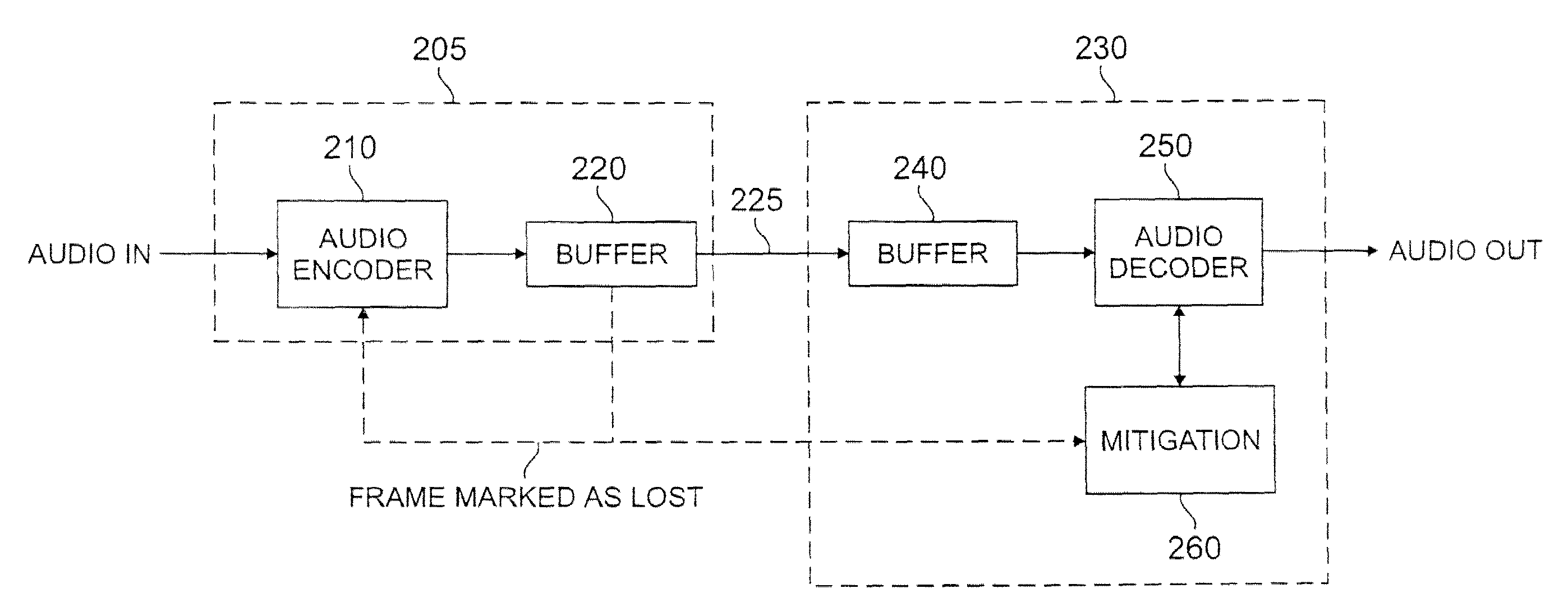
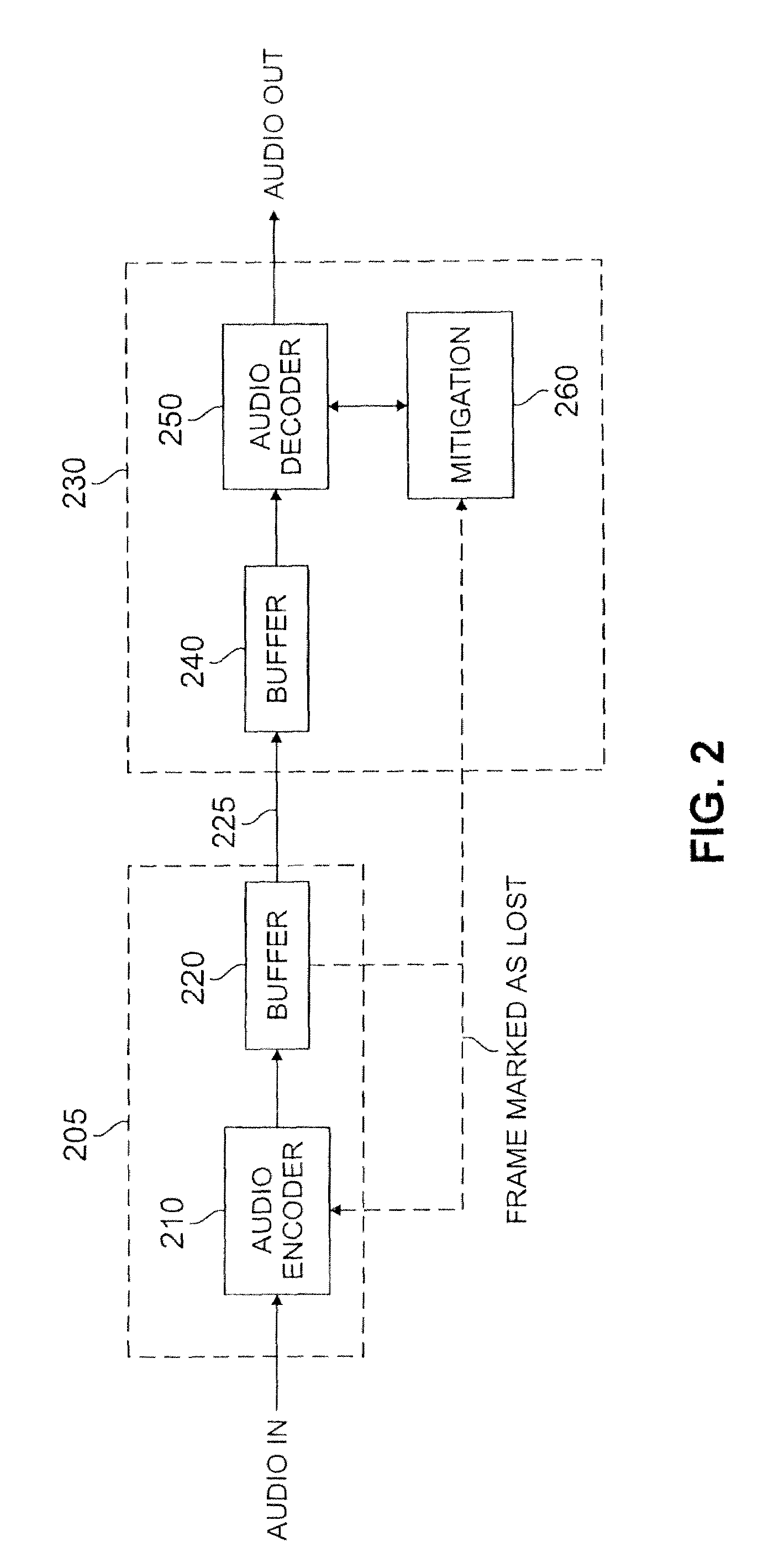
[0015]FIG. 2 illustrates a multiple channel DAB communication system 200 in accordance with the present invention. As shown in FIG. 2, the DAB communication system 200 includes a transmitter 205 having an audio encoder 210 and a buffer 220 and a receiver 230 having a buffer 240 and an audio decoder 250. A control loop (not shown) modifies the bit rate of the encoder 210 and prevents the encoder 210 from overflowing or underflowing the decoder buffer 240.

[0016]According to one aspect of the present invention, the audio encoder 210 marks a frame as “dropped” whenever an overflow of the encoder buffer 220 might occur (which corresponds to an underflow of the decoder buffer 240, due to the symmetric relationship between the encoder 210 and decoder 250). Thus, the audio encoder 210 places only a small number of bits into the buffer for the lost frame, thereby preventing a buffer overflow. In this manner, the level of the encoder buffer 220 immediately recovers from the dangerous situatio...


PUM


Abstract

A method and apparatus are disclosed for controlling a buffer in a digital audio broadcasting (DAB) communication system. An audio encoder marks a frame as “dropped” whenever a buffer overflow might occur. Only a small number of bits are utilized to process a lost frame, thereby preventing the buffer from overflowing and allowing the encoder buffer-level to quickly recover from the potential overflow condition. The audio encoder optionally sets a flag that provides an indication to the receivers that a frame has been lost. If a “frame lost” condition is detected by a receiver, the receiver can optionally employ mitigation techniques to reduce the impact of the lost frame(s).

Description

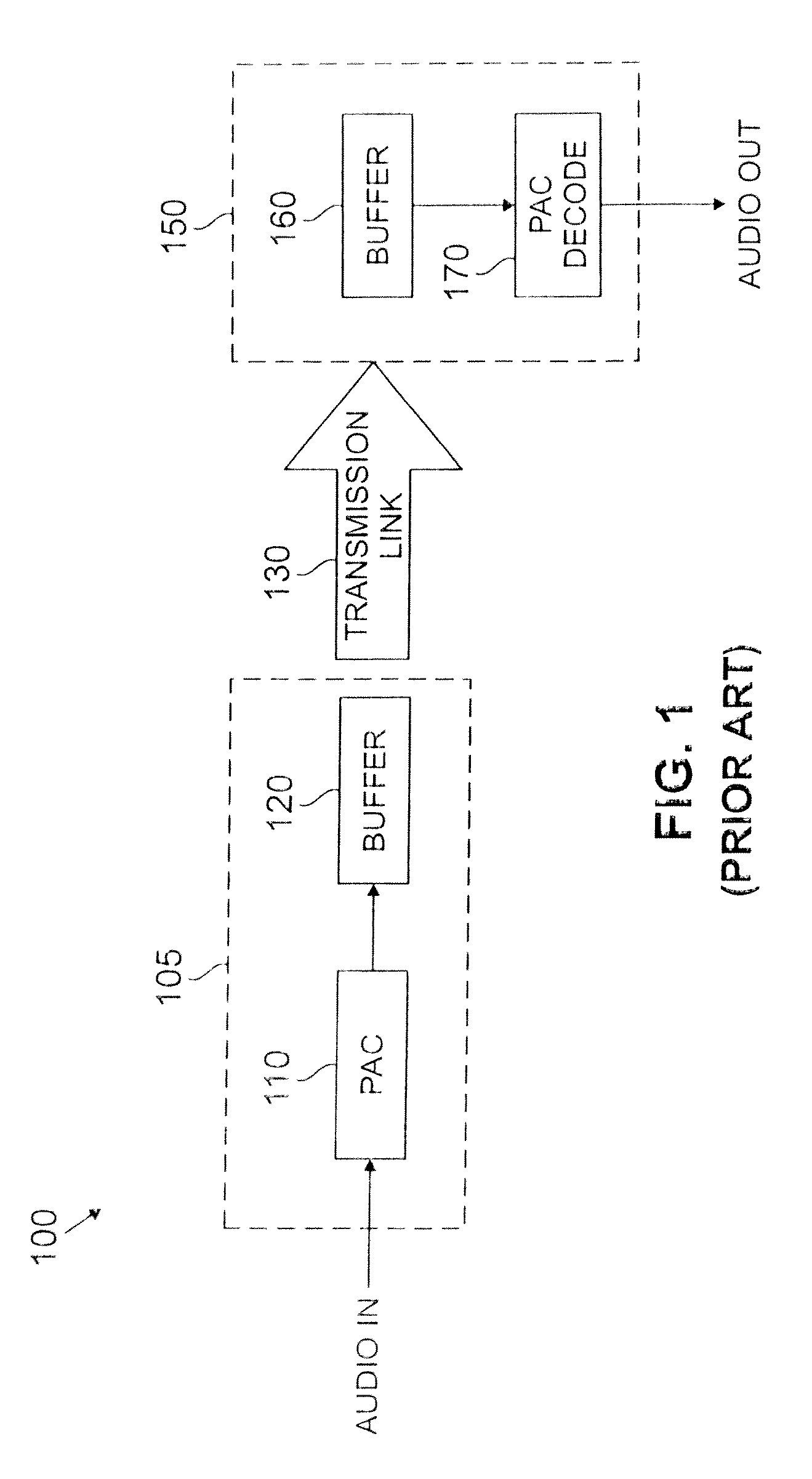
CROSS-REFERENCE TO RELATED APPLICATIONS[0001]This application is a divisional of U.S. patent application Ser. No. 09 / 895,927, filed Jun. 29, 2001, incorporated by reference herein.FIELD OF THE INVENTION[0002]The present invention relates generally to digital audio broadcasting (DAB) and other types of digital communication systems, and more particularly, to buffer control techniques for such digital audio broadcasting (DAB) and other types of digital communication systems.BACKGROUND OF THE INVENTION[0003]Proposed systems for providing digital audio broadcasting (DAB) in the FM radio band are expected to provide near compact disk (CD)-quality audio, data services and more robust coverage than existing analog FM transmissions. Digital audio broadcasting systems compress an audio signal using a digital audio encoder, such as a perceptual audio coder (PAC). Perceptual audio coders reduce the amount of information needed to represent an audio signal by exploiting human perception and min...

Claims


Application Information

Patent Timeline
Patent Type & Authority Applications(United States)
IPC IPC(8): H04L25/00H04B14/04H04H60/11H04H60/27
CPCH04B14/04H04H2201/20H04H60/27H04H60/11
Inventor FALLER, CHRISTOF
Owner AVAGO TECH INT SALES PTE LTD
Learn More