Method for centering engine structures

a technology for engines and housings, applied in machines/engines, manufacturing tools, forging/pressing/hammering apparatus, etc., can solve problems such as affecting blade tip and secondary air seal clearan

Active Publication Date: 2012-11-27
PRATT & WHITNEY CANADA CORP
View PDF46 Cites 5 Cited by
  • Summary
  • Abstract
  • Description
  • Claims
  • Application Information

AI Technical Summary

Problems solved by technology

Assembly stack up may affect the concentricity of engine structures, such as the concentricity of the bearing housings with respect to the outer case of the gas turbine engine assembly, which could bring the turbine rotors off-center relative to stationary components such as turbine shrouds, thereby directly affecting the blade tip and secondary air seal clearance, among other things.

Method used


Image

  • Method for centering engine structures
  • Method for centering engine structures
  • Method for centering engine structures

Examples


Embodiment Construction

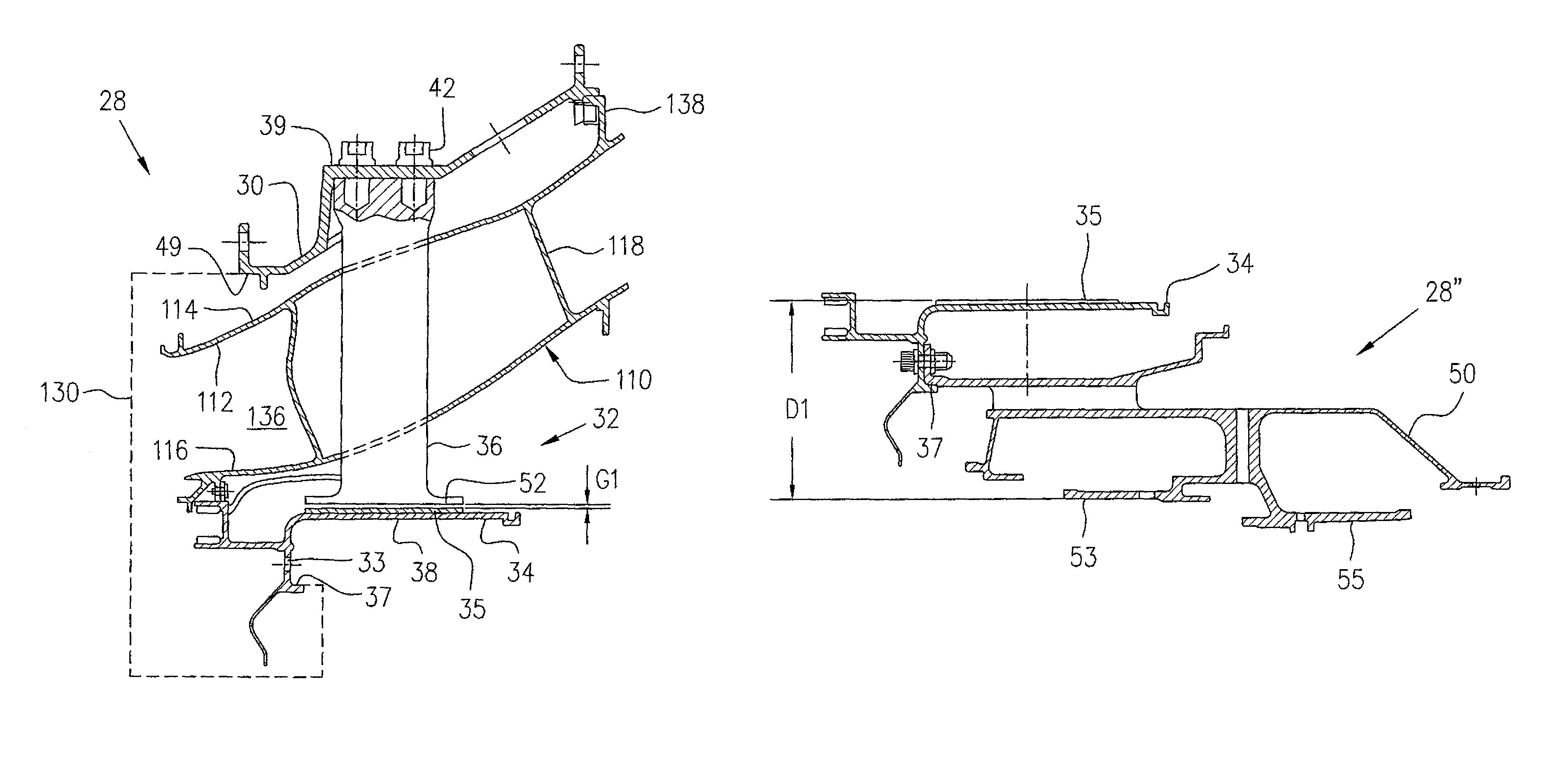
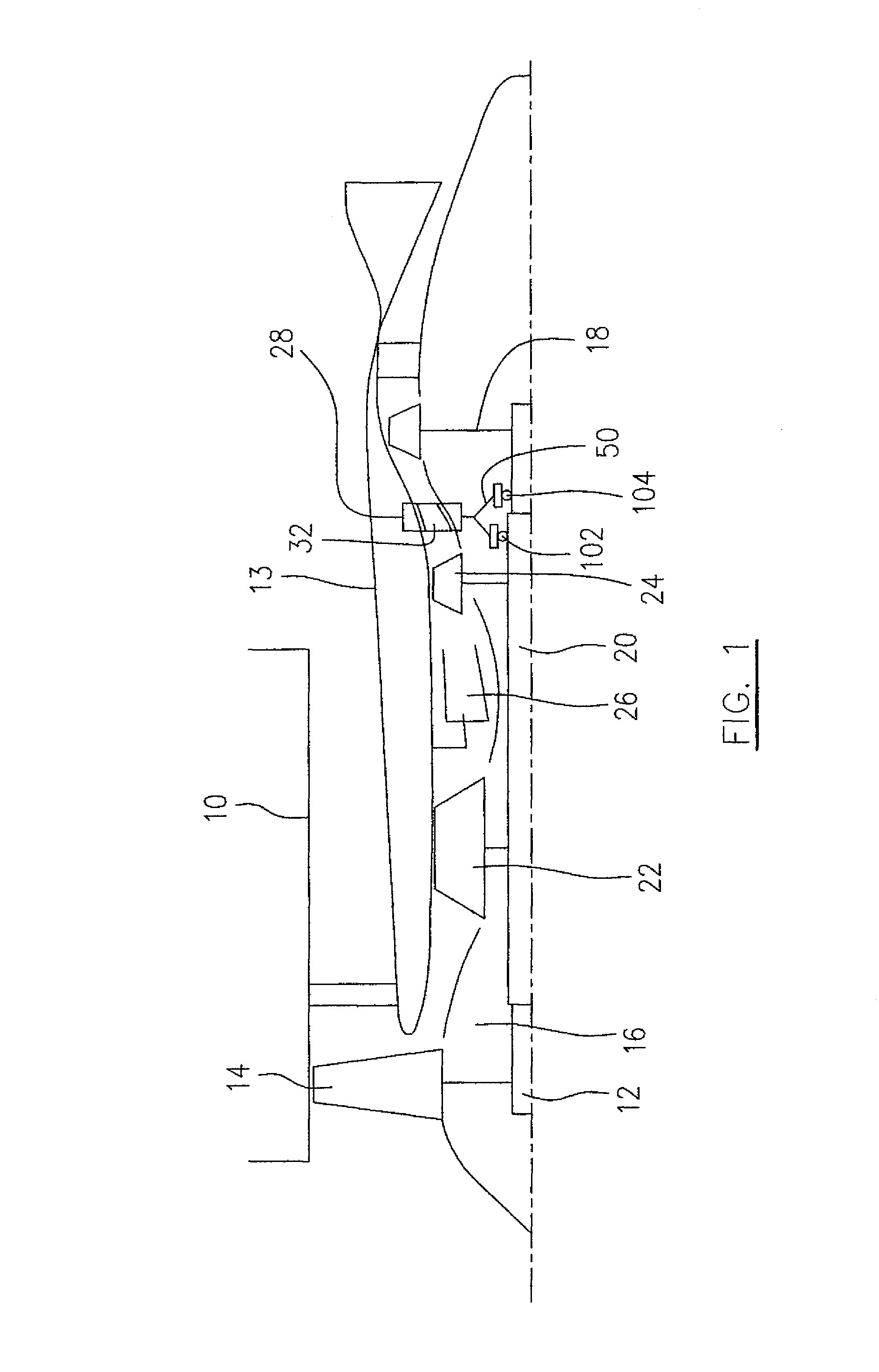
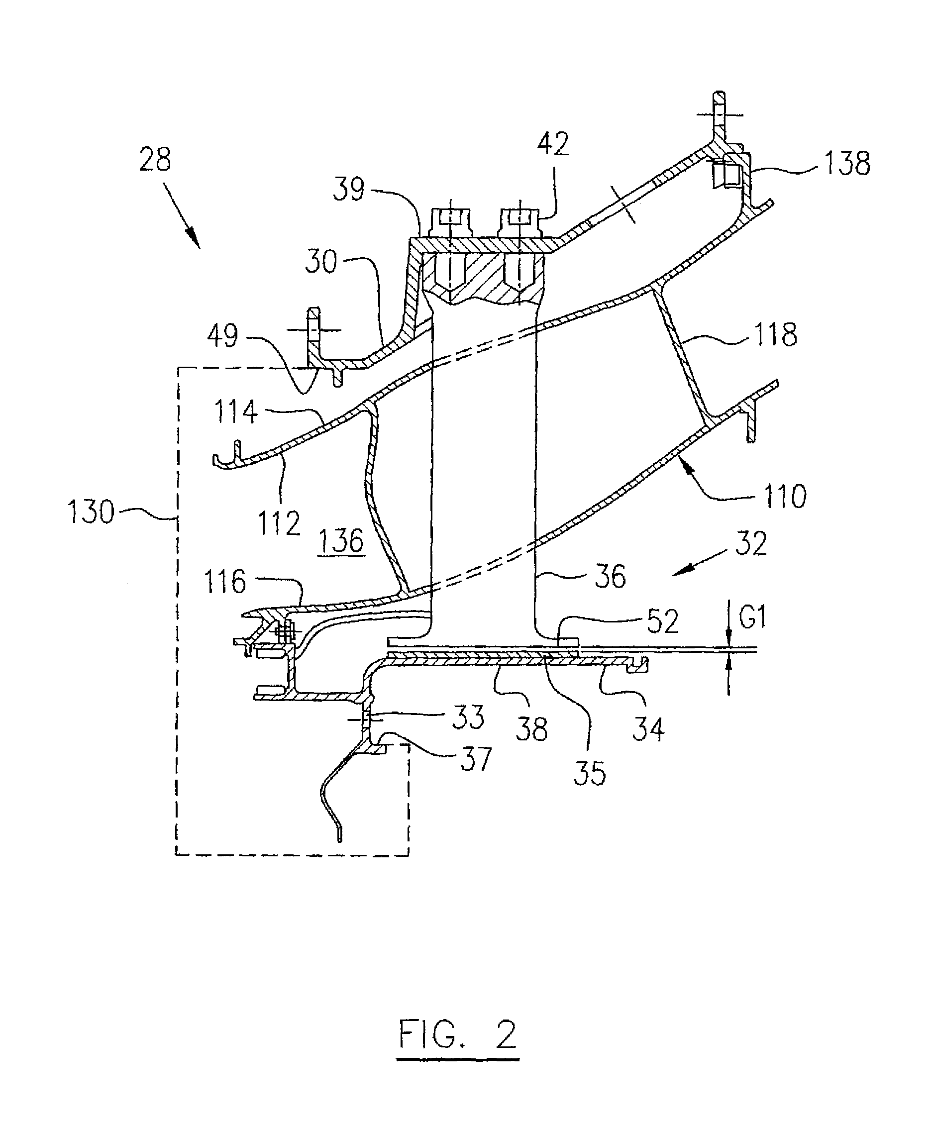
[0020]Referring to FIG. 1, a turbofan gas turbine engine includes a fan case 10, an engine core case 13, a low pressure spool assembly which includes a fan assembly 14, a low pressure compressor assembly 16 and a low pressure turbine assembly 18 connected by a shaft 12, and a high pressure spool assembly which includes a high pressure compressor assembly 22 and a high pressure turbine assembly 24 connected by a turbine shaft 20. The core casing 13 surrounds the low and high pressure spool assemblies to define a main fluid path therethrough. In the main fluid path there is provided a combustor 26 to generate combustion gases to power the high pressure turbine assembly 24 and the low pressure turbine assembly 18. A portion of the core case 13 in this example engine, includes a mid turbine frame portion 28 disposed generally between the high pressure turbine assembly 24 and the low pressure turbine assembly 18 and supports a bearing housing 50 containing, for example, bearings 102 and ...


PUM

PropertyMeasurementUnit
radial distance D1aaaaaaaaaa
inner diameteraaaaaaaaaa
radial distance D2aaaaaaaaaa

Abstract

A method for centering an engine structure such as a bearing housing is provided which may be used, for example, during assembly of a mid turbine frame or other engine case structure. In one aspect, the method includes using spacers with respective radial spokes which connect inner and outer portions of the case. In another aspect, centring may be provided by machining selected contacting surfaces of selected components.

Description

TECHNICAL FIELD[0001]The described subject matter relates generally to gas turbine engines and, more particularly, to an improved method for centering concentric cases or housings.BACKGROUND OF THE ART[0002]Assembly stack up may affect the concentricity of engine structures, such as the concentricity of the bearing housings with respect to the outer case of the gas turbine engine assembly, which could bring the turbine rotors off-center relative to stationary components such as turbine shrouds, thereby directly affecting the blade tip and secondary air seal clearance, among other things.[0003]Accordingly, there is a need to provide an improved method for centering turbine engine cases.SUMMARY[0004]In accordance with one aspect, the described subject matter provides a method for positioning outer and inner cases of a gas turbine engine relative to one another, the outer and inner cases having a plurality of radial spokes extending between them when the outer and inner cases are assem...

Claims


Application Information

Patent Timeline
Patent Type & Authority Patents(United States)
IPC IPC(8): F01D25/04F01D25/28
CPCF01D25/28F01D25/16F05D2230/64Y10T29/49861Y10T29/4932Y10T29/49771Y10T29/4978Y10T29/49229
Inventor DUROCHER, ERICPIETROBON, JOHNGRIVAS, NICOLAS
Owner PRATT & WHITNEY CANADA CORP
Why Eureka
Try Eureka