Shuttlecock

A badminton and head technology, applied in the field of badminton, can solve problems such as restrictions

Active Publication Date: 2014-04-09
SHEFFIELD HALLAM UNIVERSITY +1
View PDF4 Cites 5 Cited by
  • Summary
  • Abstract
  • Description
  • Claims
  • Application Information

AI Technical Summary

Problems solved by technology

These outdoor shuttlecocks are generally designed to be used with traditional badminton rackets, which to a considerable extent limit the additional weights that can be applied to reduce th

Method used


Image

  • Shuttlecock
  • Shuttlecock
  • Shuttlecock

Examples


Embodiment Construction

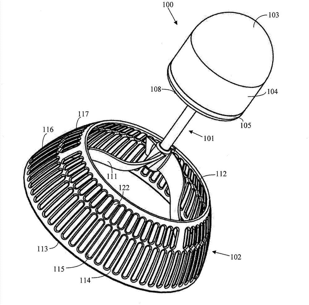
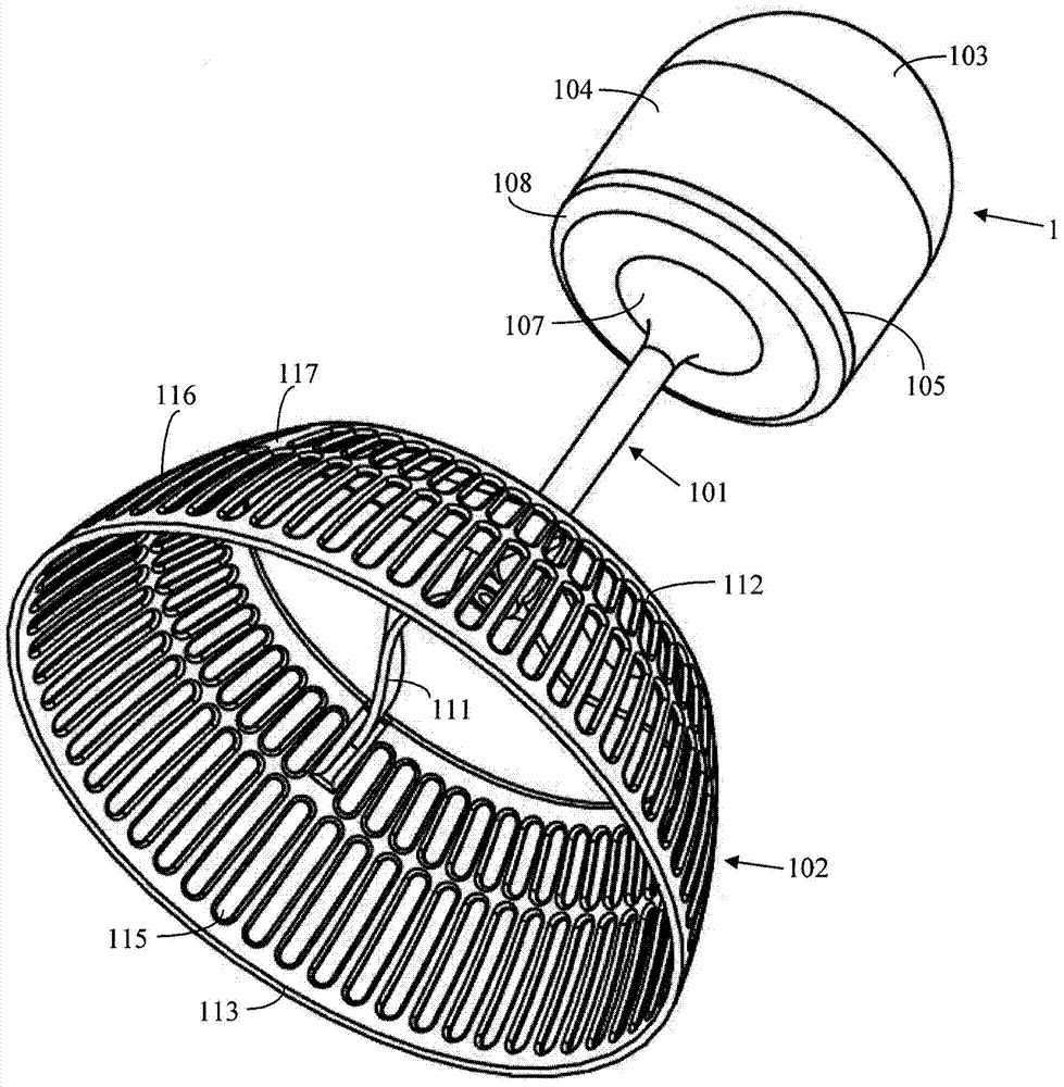
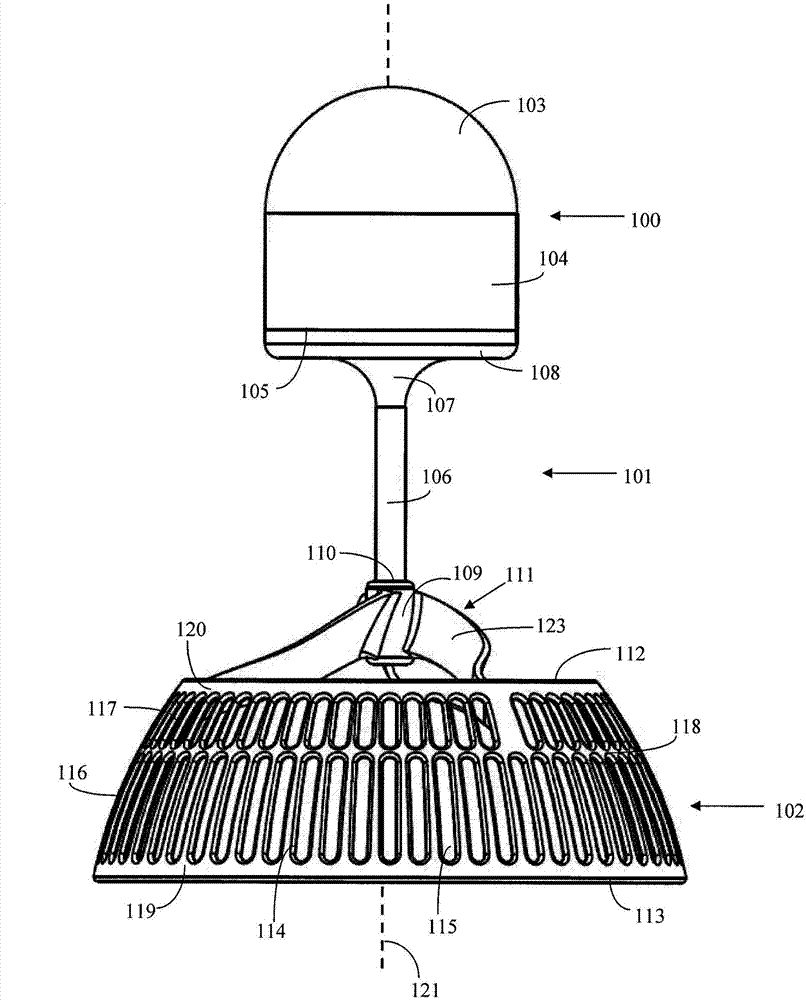
[0040] refer to Figures 1A to 3B , The shuttlecock includes three basic components: a head 100, a skirt 102 and an intermediate shaft 101 extending between the head 100 and the skirt 102. The head 100, shaft 101 and skirt 102 are co-aligned along a longitudinal axis 121 bisected centrally through the shuttlecock.

[0041] The head 100 has a dome-shaped upper region 103 which provides the strike zone of the area of ​​the shuttlecock intended to come into contact with the shuttlecock racket. A cylindrical portion 104 extends immediately below the dome 103 and terminates at a base 105 . The shaft 101 has a straight elongated portion 106 that tapers or flares out at an upper region 107 . The funnel region 107 terminates at an annular disk 108 extending radially from the elongated shaft 106 . A hollow cylindrical tongue 200 extends from the upper facing surface of the disc 108 and includes an annular lip 201 extending circumferentially around the upper edge of the tongue 200 . ...


PUM


Abstract

A shuttlecock and in particular an outdoor shuttlecock having a domed head (100) and a shaft (101) separating the head from an annular skirt (102). The skirt is connected to the shaft via radial spokes (111) that extend between the skirt and one end of the shaft. A leading edge (112) of the skirt, positioned closest to the head, is separated from the head along a longitudinal axis of the shuttlecock by a distance along the length of the shaft. The radial spokes are curved along their length to provide riffling during flight and to twist to absorb an impact force when hit with a badminton racquet.

Description

technical field [0001] The present invention relates to a shuttlecock, in particular, but not exclusively, to an outdoor shuttlecock configured to exhibit improved resistance to environmental influences, including, inter alia, wind forces, during flight. Background technique [0002] Shuttlecocks exist in many different forms, which are mainly divided into two categories, natural and synthetic. Shuttlecocks made from natural materials are usually preferred by the most experienced players and are used for all high level indoor games. These shuttlecocks usually have a cork head encased in goat hide, with the "shuttle" area formed by goose feathers. [0003] Shuttlecocks, both natural and synthetic, are very sensitive to air resistance during flight, which in turn includes altitude, humidity, temperature and air flow factors. These latter environmental conditions have a profound impact on the shuttlecock's trajectory performance and flight direction and speed when used outdoo...

Claims


Application Information

Patent Timeline
IPC IPC(8): A63B67/18
CPCA63B67/18A63B2243/0087A63B67/187A63B67/193A63B2102/04
Inventor 约翰·霍华德·哈特史蒂芬·乔治·伍德尼克·汉密尔顿
Owner SHEFFIELD HALLAM UNIVERSITY
Why Eureka
Try Eureka