Wood-type golf club head

a golf club head and wood-type technology, applied in the field of wood-type golf club heads, can solve the problems of too high spin rate, and achieve the effect of preventing effective errors in hitting the ball and high resistance to slippag

Inactive Publication Date: 2009-05-28
BRIDGESTONE SPORTS
View PDF11 Cites 142 Cited by
  • Summary
  • Abstract
  • Description
  • Claims
  • Application Information

AI Technical Summary

Benefits of technology

[0012]In this way, the invention is characterized in that the preventive elements which exhibit the high resistance to slip relative to water secreted from the hand of the golfer and water which penetrates into the golf glove in wet weather are affixed to the specific locations on the inner surface of at least the portions on the palm side area or the back side area of the glove main body with which the grip portion of the golf club is brought into abutment, whereby the stable grip is obtainable under every condition, thereby making it possible to prevent effectively an error in hitting a ball.

Problems solved by technology

More specifically, it is said that, current balls have spin rates too high to hit a long ball, and it is also said that a combination of current golf club and golf ball does not realize a launch angle and a spin rate which make the most of a ball initial velocity.

Method used


Image

  • Wood-type golf club head
  • Wood-type golf club head
  • Wood-type golf club head

Examples


Embodiment Construction

[0027]Hereinafter, preferred embodiments of the present invention will be described with reference to the drawings.

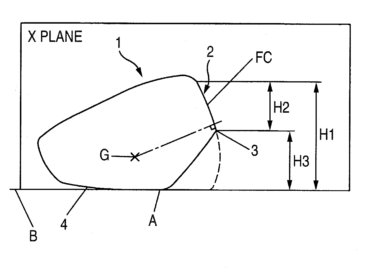
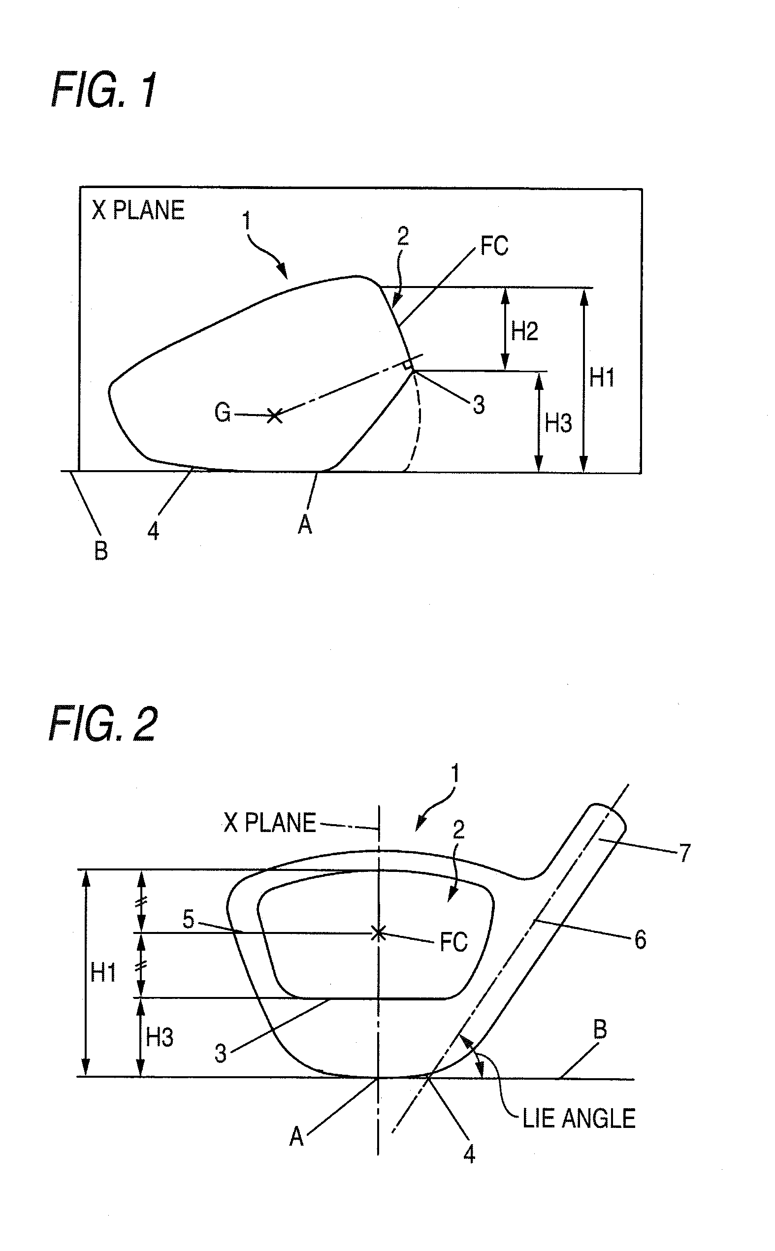
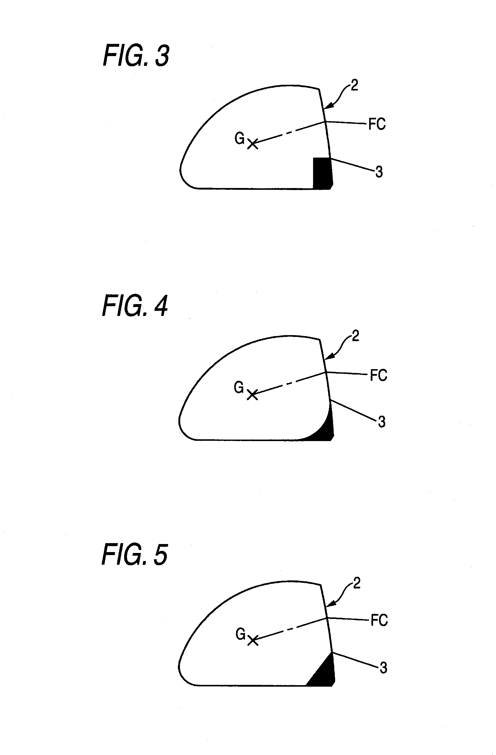
[0028]FIG. 1 shows a lateral view of a head body 1, and FIG. 2 shows a front view of the head body 1, with a leading edge 3 formed to be located at a higher position compared with a normal head. In FIG. 1 and FIG. 2, there is shown a state in which the head body 1 is set on a horizontal plane B at predetermined lie angle and loft angle. When the head body 1 is set in this manner, a face center FC is set at the midpoint between an upper edge and a lower edge (leading edge 3) of a face 2, which intersect a vertical plane X (shown as an “X plane” in the diagrams) passing through a ground point A between a sole 4 and the horizontal plane B and extending from the rear of the head in a target line direction serving as a target. A height measured from this ground point A to the upper edge of the face 2 is referred to as a face height H1. Further, a height measured from the lea...


PUM


Abstract

According to one embodiment, a wood-type golf club head includes: a face portion; a sole portion; a crown portion; a leading edge defined between the face portion and the sole portion; an upper edge defined between the face portion and the crown portion; wherein, at a basic state that the golf club head is set on a horizontal plane, a contact point between the horizontal plane and the sole portion is defined as a ground point, wherein a plane passing through the ground point and extending in a direction of a target line is defined as a vertical plane, wherein a height from the horizontal plane to a first intersection point where the face upper edge intersects the vertical plane is defined as a face height H1, and wherein a height H3 from the horizontal plane to a second intersection point where the vertical plane intersects the leading edge is defined in a range between ⅓ and ½ of the face height H1.

Description

CROSS-REFERENCE TO RELATED APPLICATIONS[0001]This application is based upon and claims the benefit of priority from Japanese Patent Application No. 2008-124280, filed May 12, 2008, and Japanese Patent Application No. 2007-305227, filed Nov. 27, 2007, the entire contents of which are incorporated herein by reference.BACKGROUND OF THE INVENTION[0002]The present invention relates to a wood-type golf club head. In particular, the present invention relates to a golf club head for promoting, as a driver head, the increase in flight distance.[0003]Flight distance in golf is determined by a ball initial velocity, a launch angle and a spin rate. In general, the higher the ball initial velocity, the greater the flight distance, and there exist a launch angle and a spin rate which make the most of the ball initial velocity. On the other hand, the current golf ball development aims at improvement of ball initial velocity and lower spin (reduction in spin rate) in order to obtain longer flight. ...

Claims


Application Information

Patent Timeline
Patent Type & Authority Applications(United States)
IPC IPC(8): A63B53/04
CPCA63B53/0466A63B2053/0408A63B2053/0433A63B71/146A63B53/0408A63B53/0433
Inventor KAJITA, RYOTA
Owner BRIDGESTONE SPORTS
Why Eureka
Try Eureka