
Energy assisted magnetic recording head having a near field transducer with reduced thermal protrusion

a technology of near field transducer and energy assisted magnetic recording head, which is applied in the field of magnetic recording head, can solve the problems of increasing coercivity, increasing the size of the grain, so as to prevent the protrusion-related damage of the nft and enhance the reliability of the eamr head

Active Publication Date: 2012-06-26
WESTERN DIGITAL TECH INC
View PDF23 Cites 153 Cited by
  • Summary
  • Abstract
  • Description
  • Claims
  • Application Information

AI Technical Summary

Benefits of technology

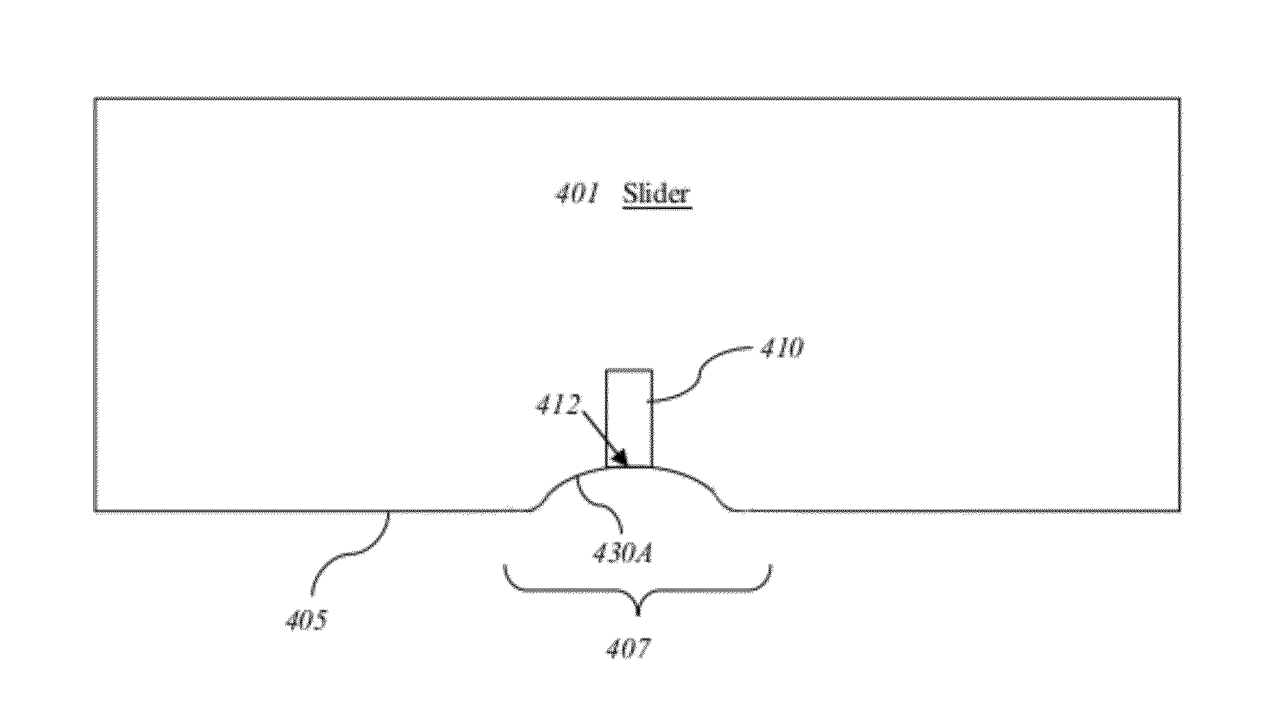
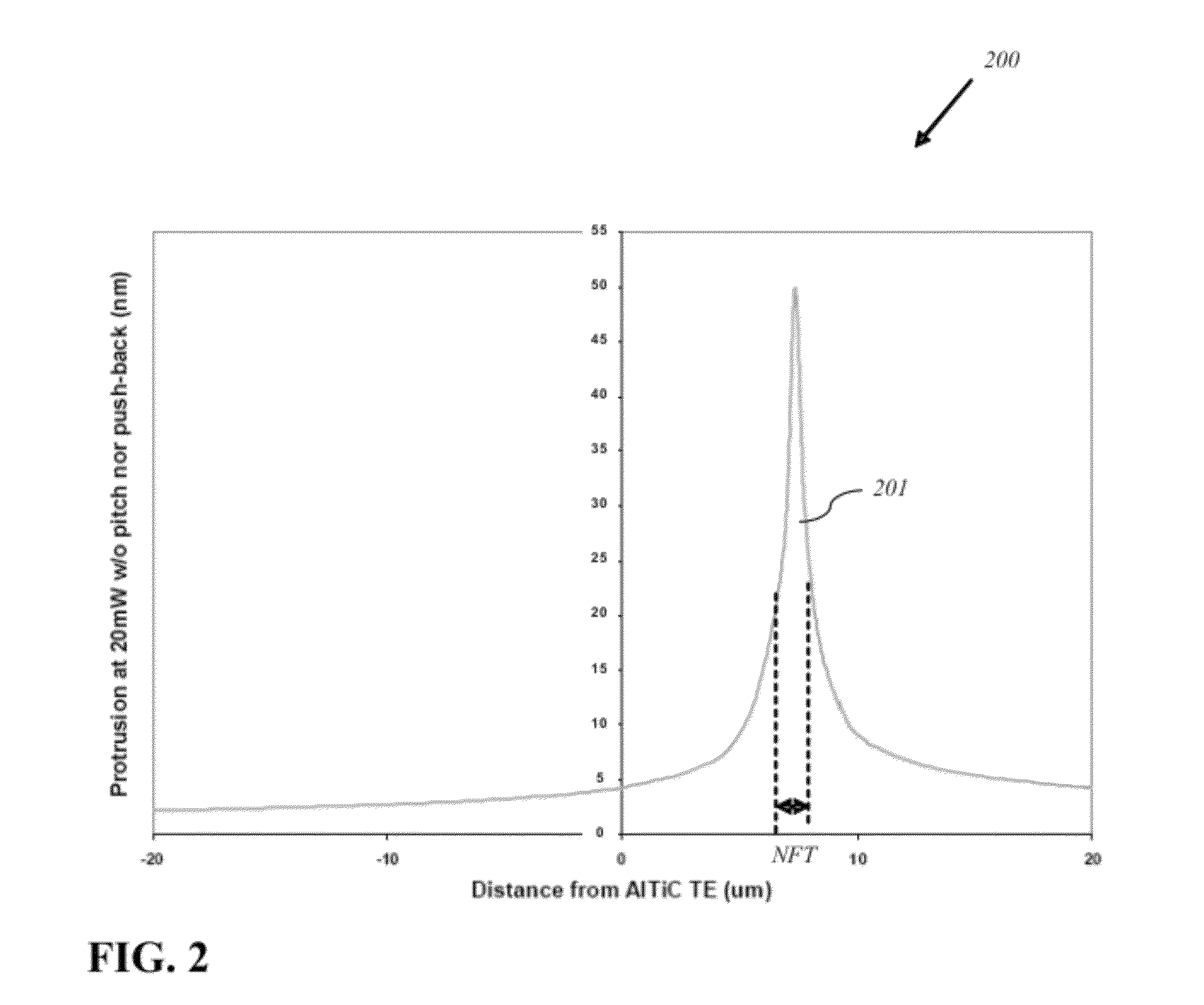
The present invention solves the problem of NFT protrusion-related damage by modifying the ABS of the EAMR head to compensate for the NFT protrusion. This approach provides a reliable method of forming EAMR heads without the aforementioned problems and greatly enhances their reliability. The method includes applying optical power to the near field transducer to generate heat, wherein the near field transducer protrudes beyond the ABS. The protruded portion of the near field transducer is then removed. The EAMR head also includes a concave surface surrounding the distal end of the near field transducer, which is formed when no optical power is applied and is coplanar with the ABS and the distal end of the near field transducer when the predetermined amount of optical power is applied.

Problems solved by technology

This reduction in grain size soon reaches a “superparamagnetic limit,” at which point the magnetic grains become thermally unstable and incapable of maintaining their magnetization.
Increasing the magnetic anisotropy of the magnetic grains, however, increases their coercivity and therefore requires a stronger magnetic field to change the magnetic orientation of the grains (e.g., in a write operation).

Method used


Image

  • Energy assisted magnetic recording head having a near field transducer with reduced thermal protrusion
  • Energy assisted magnetic recording head having a near field transducer with reduced thermal protrusion
  • Energy assisted magnetic recording head having a near field transducer with reduced thermal protrusion

Examples


Embodiment Construction

[0016]In the following detailed description, numerous specific details are set forth to provide a full understanding of the present invention. It will be apparent, however, to one ordinarily skilled in the art that the present invention may be practiced without some of these specific details. In other instances, well-known structures and techniques have not been shown in detail to avoid unnecessarily obscuring the present invention. The word “exemplary” is used herein to mean “serving as an example, instance, or illustration.” Any embodiment or design described herein as “exemplary” is not necessarily to be construed as preferred or advantageous over other embodiments or designs.

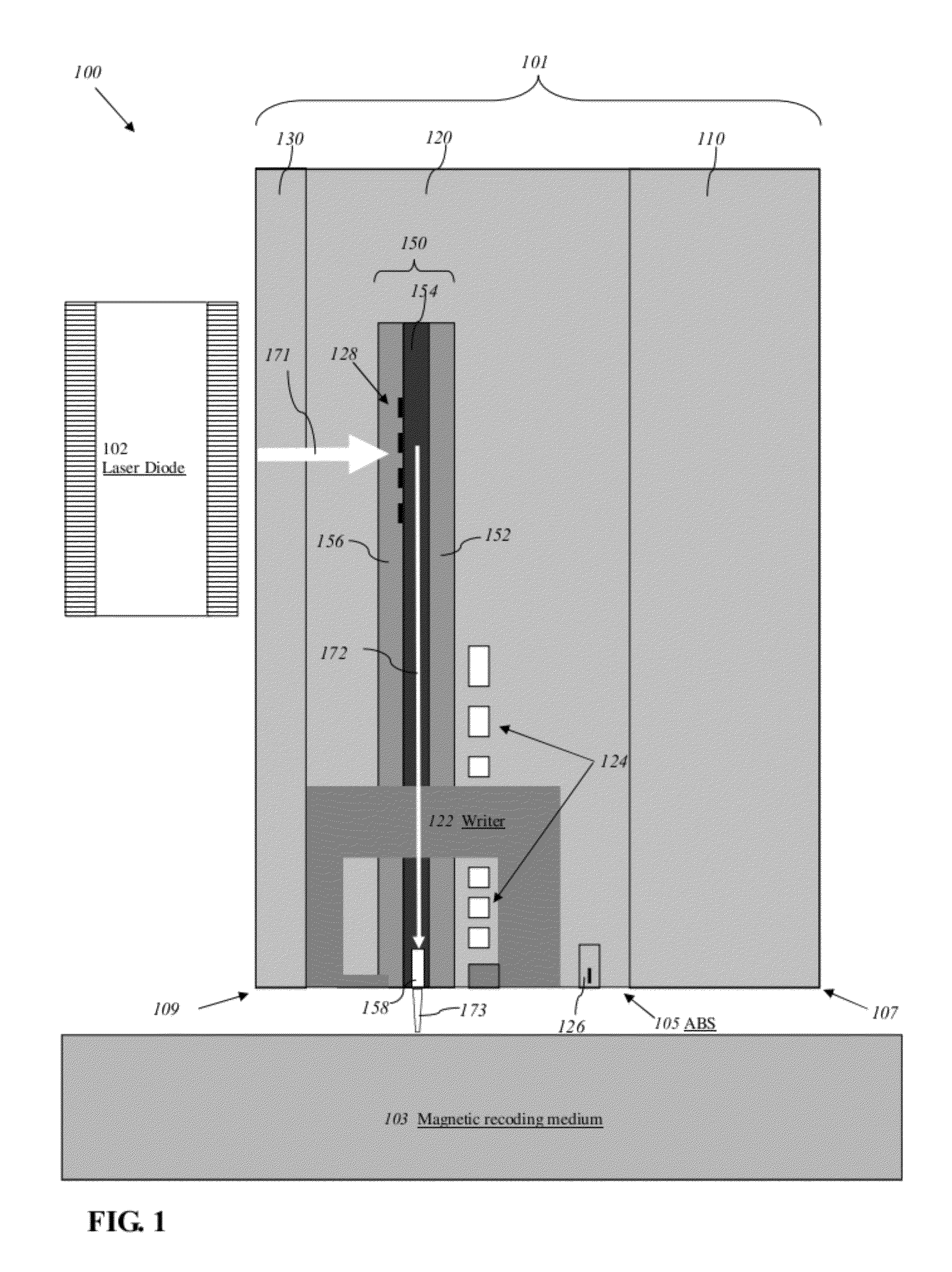
[0017]FIG. 1 is a schematic diagram illustrating an exemplary EAMR head 100 comprising a slider 101 and a near field transducer 158 according to one aspect of the subject technology. The slider 101 comprises a substrate 110, a recorder / reader layer 120 disposed over the substrate 110, and an overcoat layer 1...


PUM

PropertyMeasurementUnit
optical poweraaaaaaaaaa
areal storage densityaaaaaaaaaa
grain sizeaaaaaaaaaa

Abstract

An energy assisted magnetic recording head comprises a slider having a leading edge, a trailing edge, and an air bearing surface (ABS), and a near field transducer (NFT) disposed in the slider and having a distal end proximate the ABS. The distal end is recessed from the ABS when no optical power is applied to the NFT, and is co-planar with the ABS when a predetermined amount of optical power is applied to the NFT. A portion of the slider surrounding the distal end forms a concave surface having a continuously varying slope when no optical power is applied to the NFT, and a flat surface coplanar with the ABS and the distal end when the predetermined amount of optical power is applied to the NFT. Applying optical power comprises coupling light into a waveguide formed in the head and directing the coupled light to the NFT via the waveguide.

Description

CROSS-REFERENCE TO RELATED APPLICATION[0001]This application is a divisional of pending U.S. patent application Ser. No. 12 / 415,465, filed Mar. 31, 2009, which is incorporated herein by reference in its entirety.FIELD OF THE INVENTION[0002]The present invention generally relates to magnetic recording heads and, in particular, relates to reducing the thermal protrusion of a near field transducer (NFT) in an energy-assisted magnetic recording (EAMR) head.BACKGROUND OF THE INVENTION[0003]To increase the areal storage density of a magnetic recording device, the recording layer thereof may be provided with smaller and smaller individual magnetic grains. This reduction in grain size soon reaches a “superparamagnetic limit,” at which point the magnetic grains become thermally unstable and incapable of maintaining their magnetization. The thermal stability of the magnetic grains can be increased by increasing the magnetic anisotropy thereof (e.g., by utilizing materials with higher anisotro...

Claims


Application Information

Patent Timeline
Patent Type & Authority Patents(United States)
IPC IPC(8): G11B11/00
CPCG11B5/3136G11B5/314G11B5/3169Y10T29/49048G11B2005/0021Y10T29/49032G11B2005/001
Inventor HU, YUFENGYAN, WENTAO
Owner WESTERN DIGITAL TECH INC
Learn More