Air bearing having a cavity patch surface coplanar with a leading edge pad surface

Inactive Publication Date: 2005-04-12
WESTERN DIGITAL TECH INC
View PDF5 Cites 162 Cited by
  • Summary
  • Abstract
  • Description
  • Claims
  • Application Information

AI Technical Summary

Benefits of technology

The invention is directed to an improved air bearing surface design for a read/write head in a magnetic disk drive. The air bearing surface design includes a feature, termed a “patch,” that allows the read/write head to maintain a fly height with greater insensitivity to changes in the rotation rate of the magnetic disk and the ambient air pressure. While a read/write head employing an air bearing surface of the invention would be appropriate to a magnetic disk dri

Problems solved by technology

Unfortunately, lower fly heights also increase the likelihood that the flying rea

Method used


Image

  • Air bearing having a cavity patch surface coplanar with a leading edge pad surface
  • Air bearing having a cavity patch surface coplanar with a leading edge pad surface
  • Air bearing having a cavity patch surface coplanar with a leading edge pad surface

Examples


Embodiment Construction

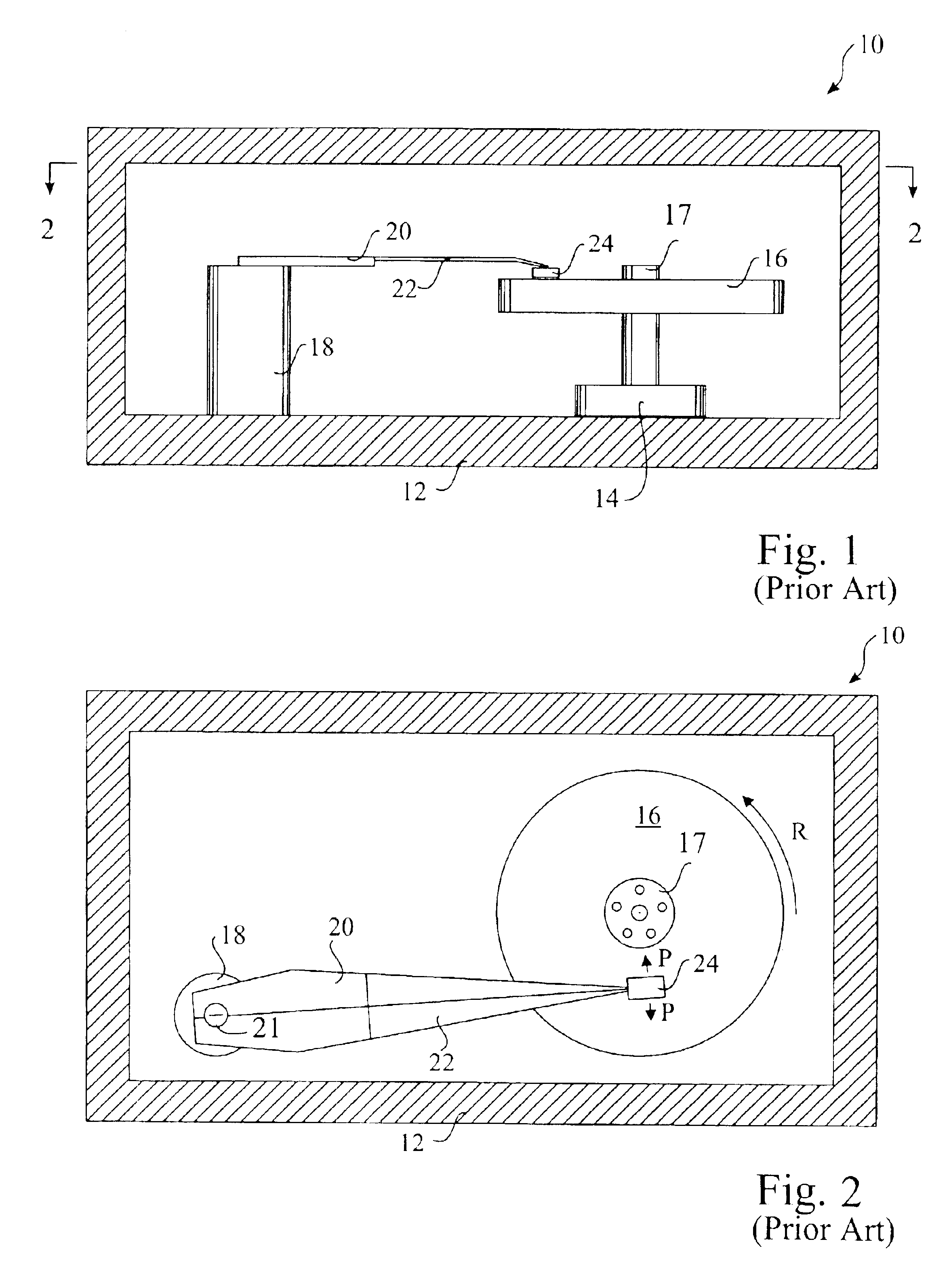
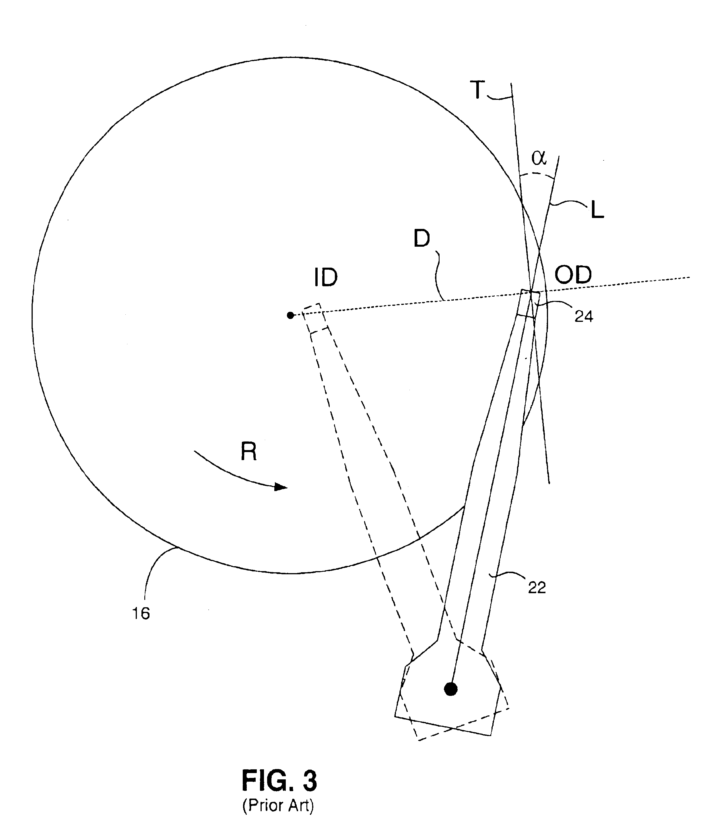
Referring back to FIGS. 1 and 2, FIG. 3 is a plan view of a read / write head 24 disposed over a magnetic disk 16 to further illustrate the range of motion of the suspension 22 and the read / write head 24 relative to the magnetic disk 16 from the inside diameter (ID) to the outside diameter (OD). An arrow R indicates the direction of spin of the magnetic disk 16 and, accordingly, the direction of the air flow past the read / write head 24. It can be seen that, from the frame of reference of the read / write head 24, as the read / write head 24 is translated from ID to OD the direction of the air flow beneath it changes. Further, as the read / write head 24 is translated from ID to OD the velocity of the air flow increases. Accordingly, the read / write head 24 needs to be designed to maintain a desired fly height under conditions of changing air flow velocity and direction.

The orientation of the read / write head 24 around a vertical axis is a parameter called skew. Specifically, a skew angle α is...


PUM


Abstract

An air bearing surface for read/write head of a magnetic disk drive is disclosed. The air bearing surface includes a trailing edge pad and a leading edge pad with trailing portions. A cavity is defined between the trailing edge pad and the trailing portions of the leading edge pad. A cavity patch is disposed within the cavity. The cavity patch can be disposed within the cavity towards one side of the read/write head.

Description

BACKGROUND OF THE INVENTION1. Field of the InventionThe present invention relates generally to the field of magnetic disk drives, and more particularly to a design for an air bearing surface of a read / write head for a magnetic disk drive.2. Description of the Prior ArtMagnetic disk drives are used to store and retrieve data for digital electronic apparatuses such as computers. In FIGS. 1 and 2, a magnetic disk data storage system 10 includes an enclosure 12, a disk drive motor 14, and a magnetic disk, or media, 16 supported for rotation by a drive spindle 17 of motor 14. Also included are an actuator 18 and an arm 20 attached to an actuator spindle 21 of actuator 18. A suspension 22 is coupled at one end to the arm 20 and at another end to a read / write head 24. The suspension 22 and the read / write head 24 are commonly collectively referred to as a head gimbal assembly (HGA). The read / write head 24 typically includes an inductive write element and a magnetoresistive read element that...

Claims


Application Information

Patent Timeline
IPC IPC(8): G11B5/60
CPCG11B5/6005
Inventor SUN, BIAOLEVI, PABLO G.
Owner WESTERN DIGITAL TECH INC
Why Eureka
Try Eureka