Coriolis mass flowmeter

a mass flowmeter and coriolis technology, applied in the field of coriolis mass flowmeters, can solve problems such as inability to vibrate, and achieve the effect of small flow rate and increased insensitivity to external vibration

Active Publication Date: 2013-02-21
KRONE GMBH
View PDF5 Cites 7 Cited by
  • Summary
  • Abstract
  • Description
  • Claims
  • Application Information

AI Technical Summary

Benefits of technology

[0005]Therefore, a primary object of the invention is to devise a Coriolis mass flowmeter which is suitable for measuring very small flow rates, and at the same time, has an increased insensitivity to external vibrations.

Problems solved by technology

The vibration sections are necessarily located outside the base since, otherwise, vibration would not be possible.

Method used


Image

  • Coriolis mass flowmeter
  • Coriolis mass flowmeter
  • Coriolis mass flowmeter

Examples


Embodiment Construction

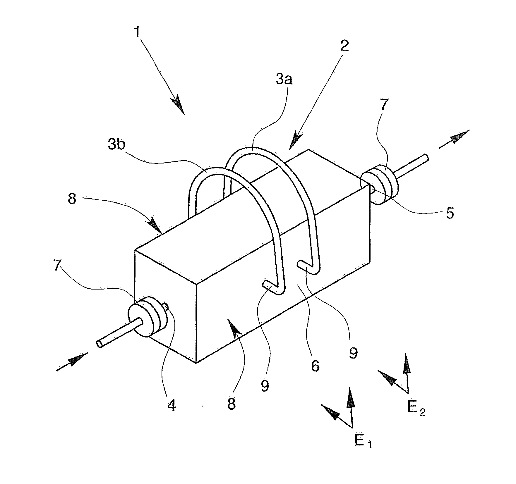
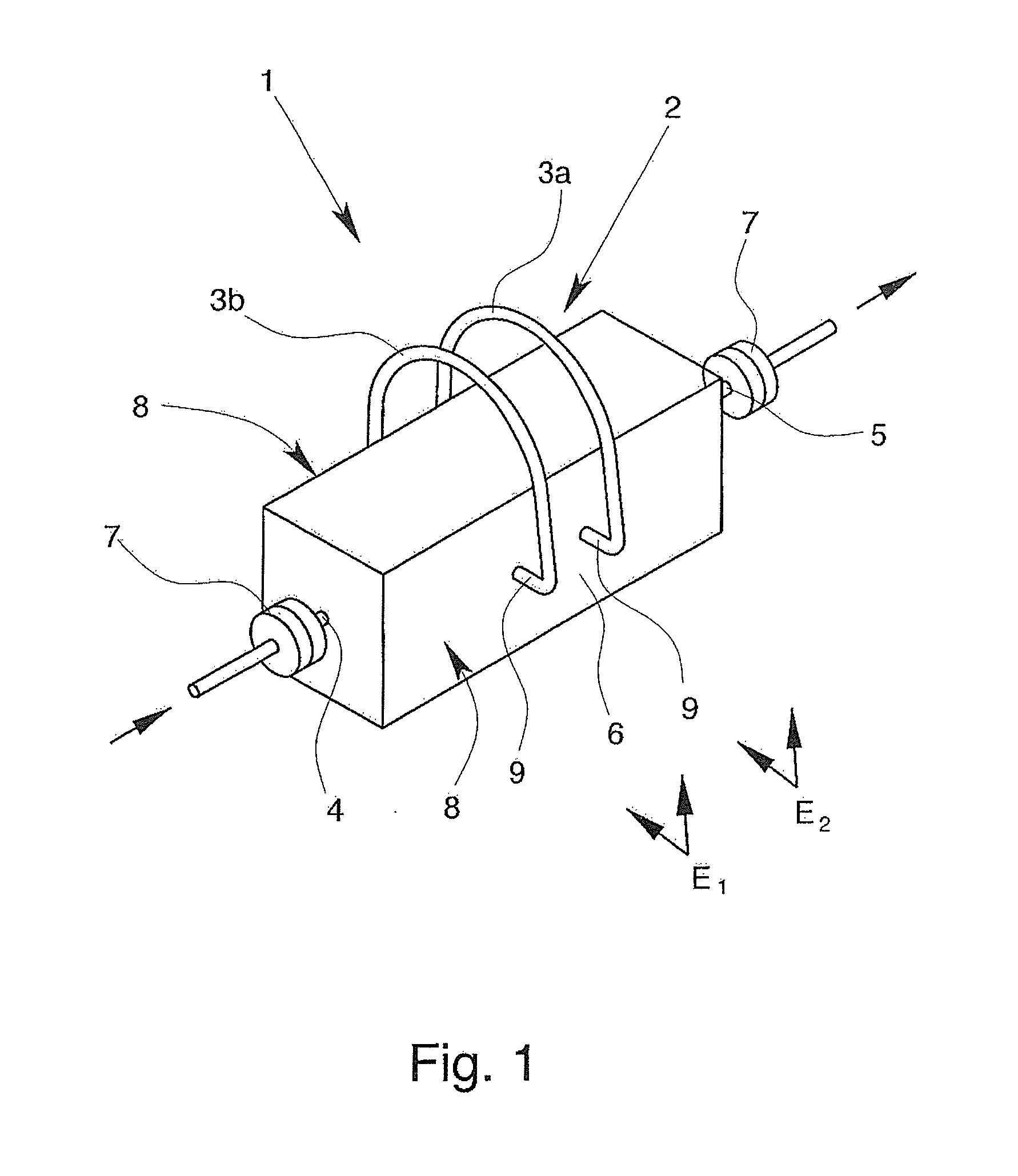
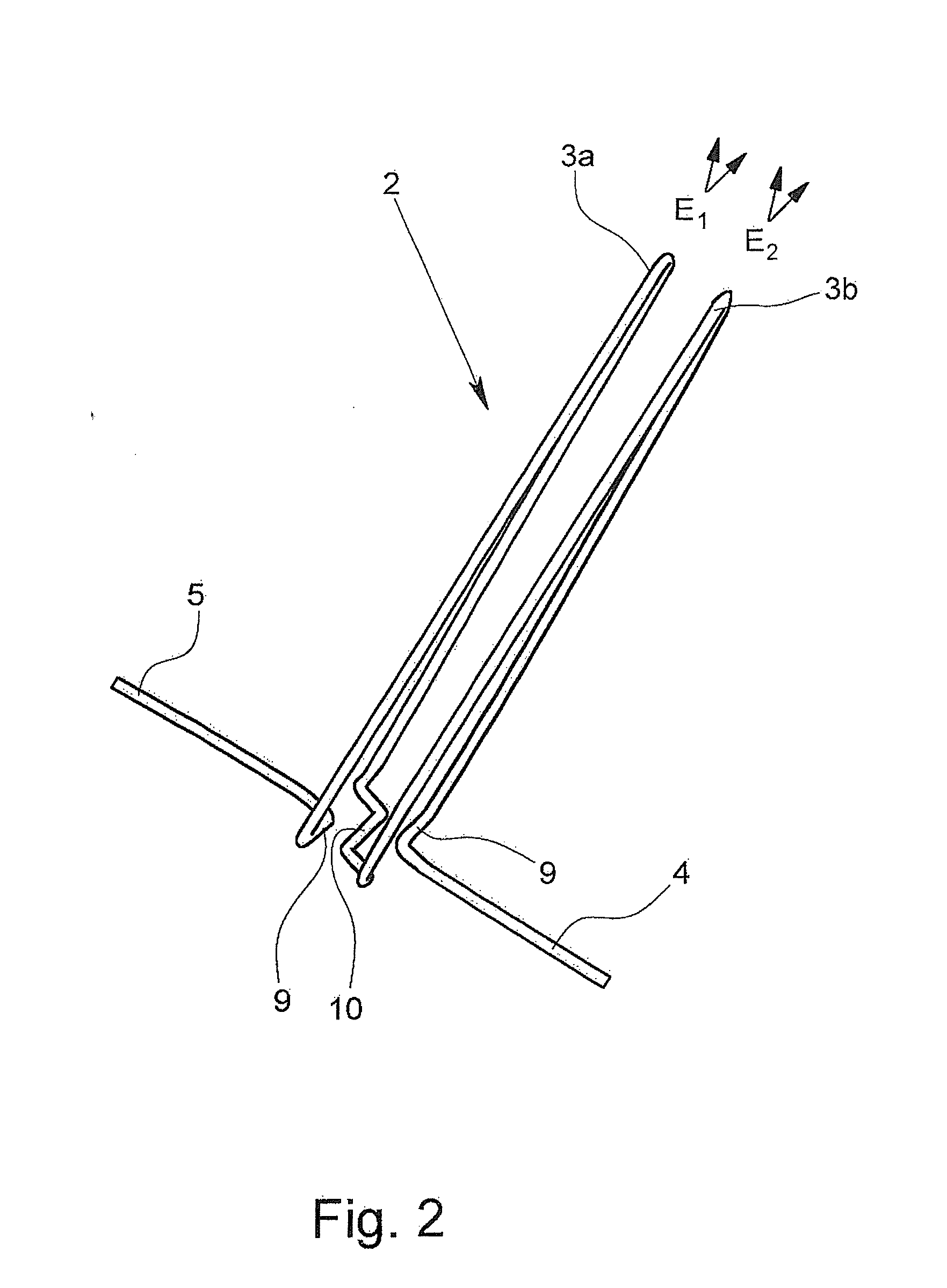
[0032]FIG. 1 shows an exemplary embodiment of a Coriolis mass flowmeter 1 with a measurement tube 2 for forming a flow channel through which the medium which is to be measured flows. The vibration generators and vibration pick-ups which are attached to the vibration sections 3 and which run in parallel planes E1, E2 are conventional in construction and use, and thus, are only schematically depicted in FIG. 5. The first vibration section 3a and the second vibration section 3b can be set into vibrations in phase opposition by the vibration generator. The measurement tube 2, except for the vibration sections 3a, 3b, an inlet end 4 and an outlet end 5, is located within a solid base 6. On the inlet end 4 and on the outlet end 5 there are flanges 7 which are used to connect the Coriolis mass flowmeter 1 to the surrounding pipeline system. The pipeline system is represented by arrows in FIG. 5.

[0033]The flow channel is formed exclusively by a single measurement tube 2 which runs essential...


PUM


Abstract

A Coriolis mass flowmeter with at least one measurement tube (2) for forming a flow channel, at least one vibration generator and at least one vibration pick-up, the measurement tube (2) having one inlet end (4), two vibration sections (3a, 3b) and one outlet end (5) and being bent at least in sections such that two U-shaped or V-shaped vibration sections (3a, 3b) which run in essentially parallel planes are formed, and the vibration sections (3a, 3b) can be excited to vibrations by the vibration generator. The flow channel, except for the inlet end (4), the vibration sections (3a, 3b) and the outlet end (5), runs within a solid base (6).

Description

BACKGROUND OF THE INVENTION[0001]1. Field of the Invention[0002]The invention relates to a Coriolis mass flowmeter with at least one measurement tube for forming a flow channel, at least one vibration generator and at least one vibration pick-up, the measurement tube having an inlet end, two vibration sections and an outlet end and being bent at least in sections such that two U-shaped or V-shaped vibration sections which run in essentially parallel planes are formed, and the vibration sections being excited to vibrations by the vibration generator.[0003]2. Description of Related Art[0004]Coriolis mass flowmeters have been known for a long time in a host of configurations. For mass flowmeters which are based on the Coriolis principle, the measurement tube through which a medium can flow or the measurement tubes through which a medium can flow are excited by a vibration generator to a vibration which preferably corresponds to a certain natural resonance frequency. On the inlet and ou...

Claims


Application Information

Patent Timeline
Patent Type & Authority Applications(United States)
IPC IPC(8): G01F1/84
CPCG01F1/8413G01F15/18G01F1/8486
Inventor HUSSAIN, YOUSIFWANG, TAO
Owner KRONE GMBH
Why Eureka
Try Eureka