Eureka AIR delivers breakthrough ideas for toughest innovation challenges, trusted by R&D personnel around the world.

Self-balancing frequency determining bridge

a frequency determining bridge and self-balancing technology, applied in the direction of reference comparison, resistance/reactance/impedence, instruments, etc., can solve the problems of slowness, complex and expensive, and inability to automatically apply calibration factors as a result of measuring frequency, etc., to achieve good frequency range, good frequency insensitivity, and excellent match

Active Publication Date: 2010-01-14
LADYBUG TECH
View PDF5 Cites 10 Cited by
  • Summary
  • Abstract
  • Description
  • Claims
  • Application Information

AI Technical Summary

Benefits of technology

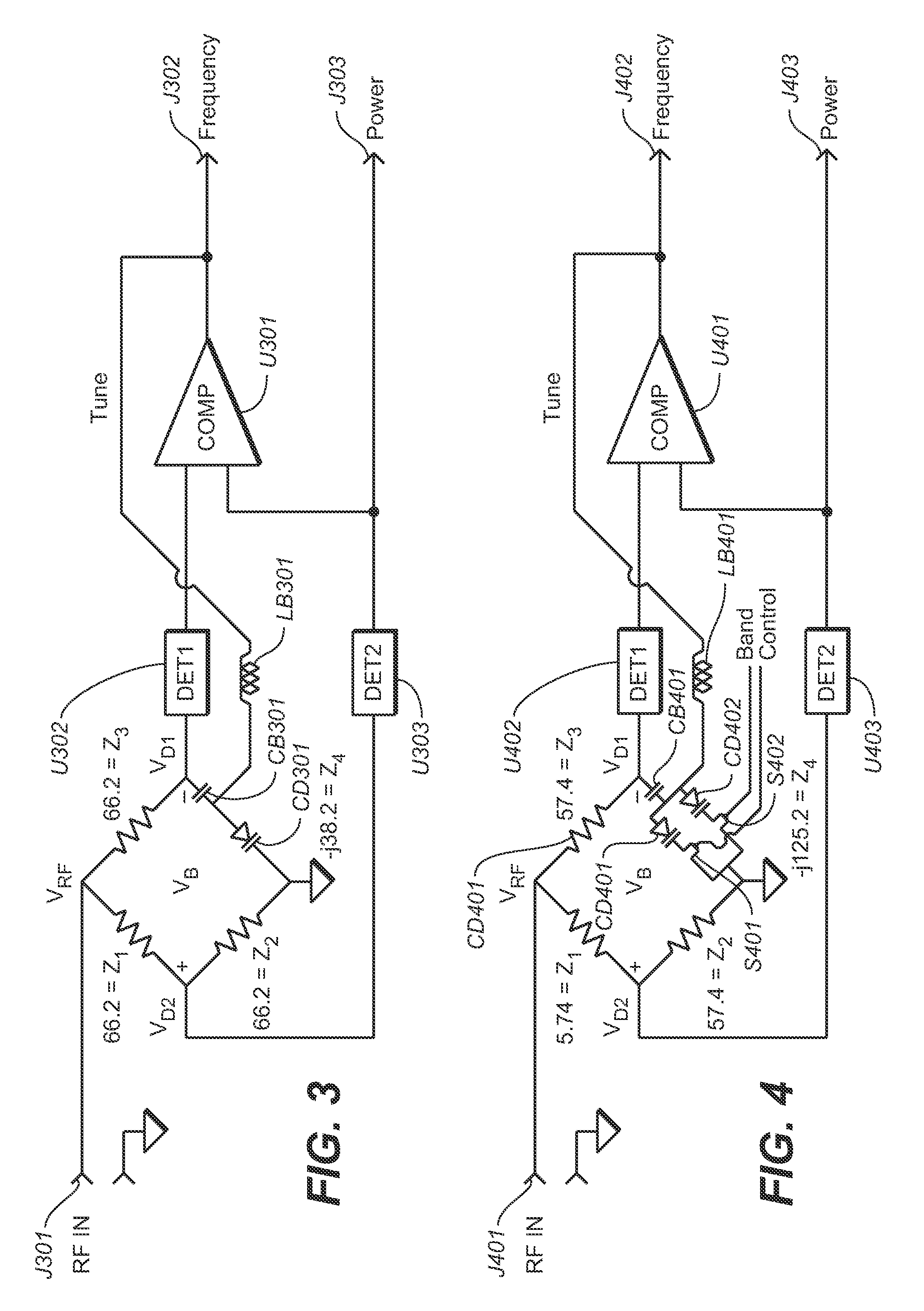
[0016]In several preferred embodiments a number of microwave switches (including microwave FETs) may be employed to allow reactive legs to be switched in or out in order to cover a broader frequency range. Preferably the switched legs are positioned so that a resistive leg is between RFin and the switched leg. This provides some isolation from switching transients. In all cases this approach yields excellent match at the frequency of interest, very good frequency insensitivity, good frequency range, good dynamic range, is highly responsive (or as unresponsive as desired) and is relatively simple.

Problems solved by technology

In any event, the automatic application of calibration factors as a result of measuring frequency is not a novel idea.
However, these approaches have the following problems: (1) they tend to be slow; (2) they are very complex and expensive (usually as complex as the power meter itself); and (3) they are difficult to employ at low power and high frequency.
The disclosed method has a few notable limitations: (1) Match is an important specification for any power sensor, and it is difficult to design filter that provides a broadband match to incoming signals (this would be problematic for power sensors); (2) while the filter is in the pass band it is difficult to reliably differentiate frequency based on level.
Beyond the knee of the filter, sensitivity becomes a serious problem.
These two limitations may make frequency determination too inaccurate in most cases, and simply impossible in some cases.
This is because sensitivity varies with frequency (as previously mentioned), and as a result the useable power range is very limited.
This causes additional problems with match or reflection and complexity.
This results in an expensive and time consuming proposition since the filter-detector pair must be calibrated over power and temperature.
And further still, the complexity of the firmware is greatly increased.
These approaches are either excessively complex, have very serious match problems, are unable to deal with a wide dynamic range, or suffers another fundamental limitation.

Method used


Image

  • Self-balancing frequency determining bridge
  • Self-balancing frequency determining bridge
  • Self-balancing frequency determining bridge

Examples


Embodiment Construction

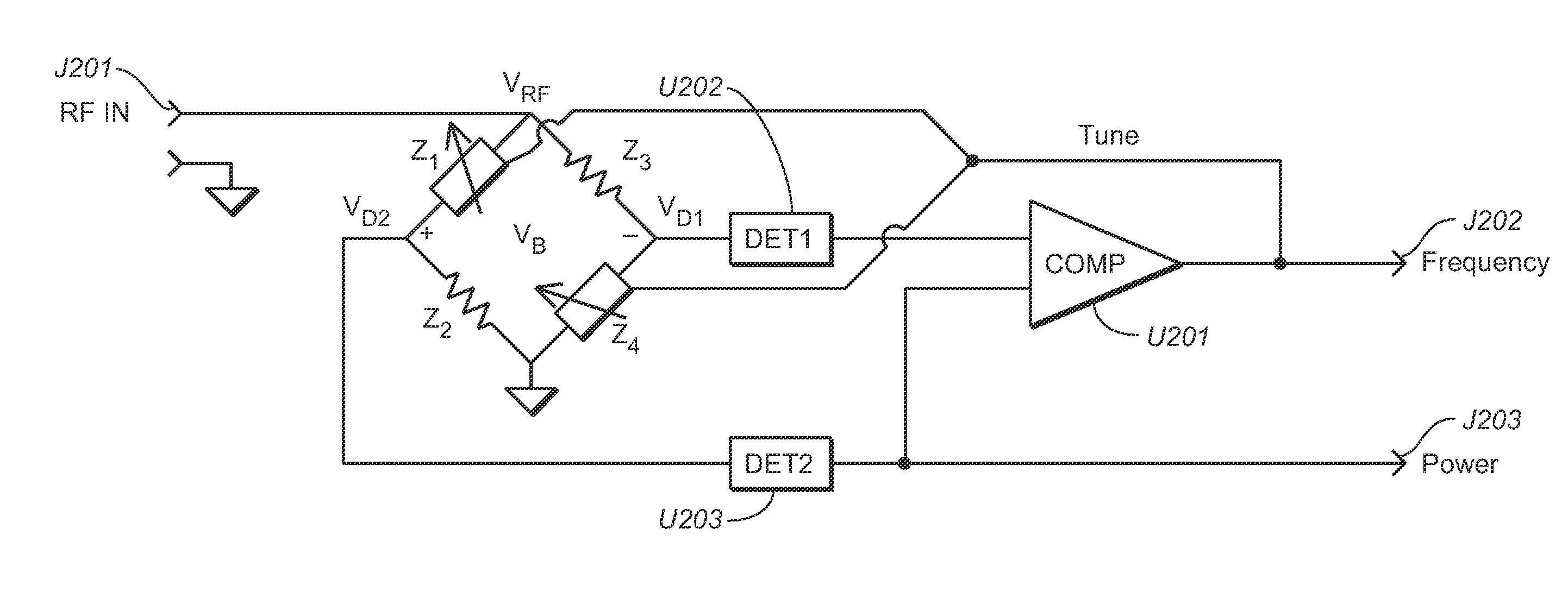
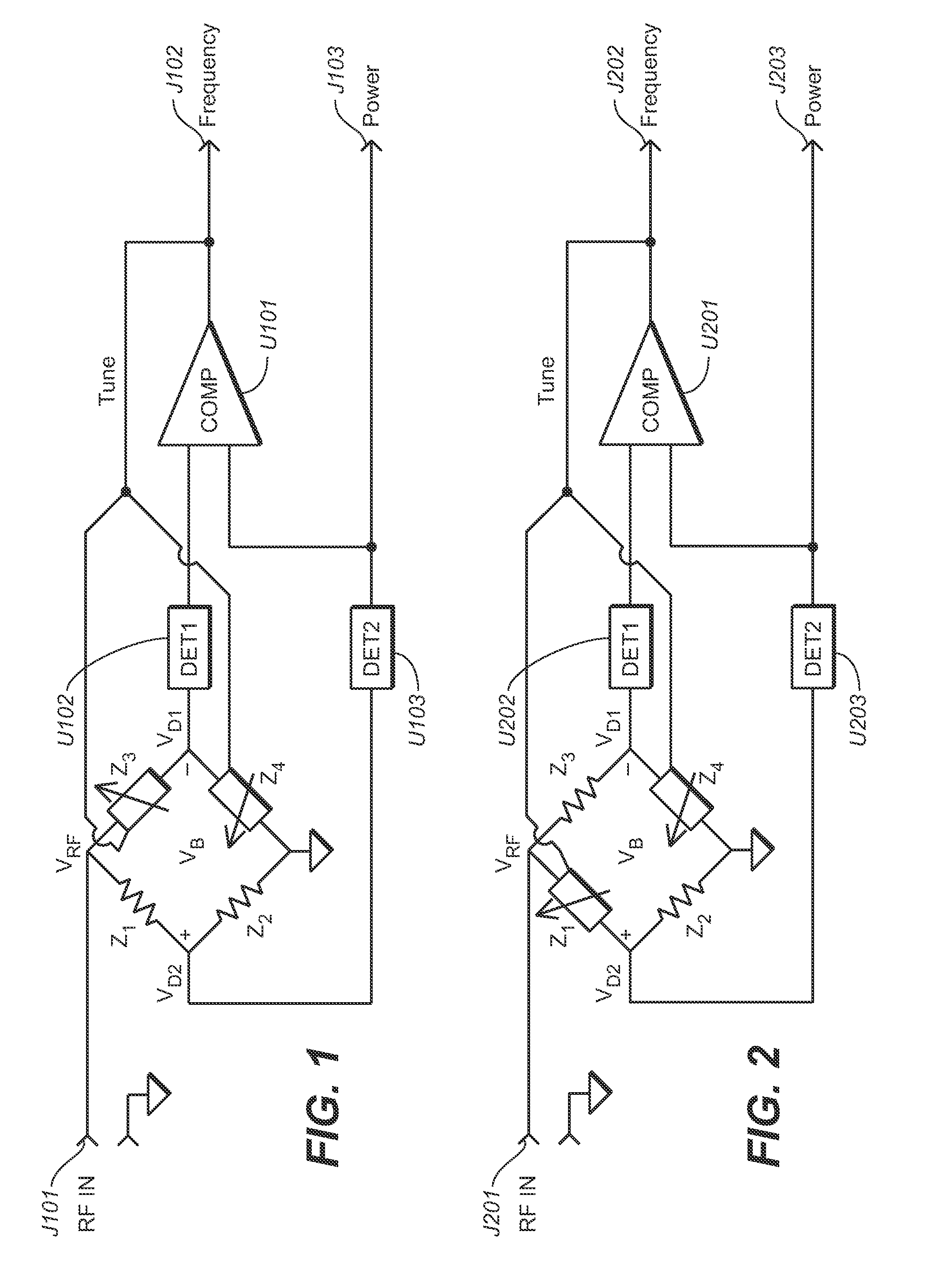
[0047]Referring now to FIG. 1, there is shown a simplified schematic diagram of a first preferred embodiment of the present invention. In this embodiment, each side of a Wheatstone bridge provides impedance through voltage-controlled frequency-reactive elements Z2 and Z4, and non-reactive impedances Z1 and Z2 only, such as resistors. The junction of Z3 and Z4 are grounded in common with the ground used by RF input connection J101. A radio frequency (RF) input signal is applied to RF input connection J101. The RF input signal is passed from RF input connection J101 to the junction of Z1 and Z3

[0048]The junction of Z3 and Z4 is the input to detector U102, which then produces as its output a direct current (DC) voltage proportional to the power of the RF input signal. The output of detector U102 is coupled to one input of differential voltage comparator U101. Note that detector U102 is preferably implemented as a demodulating logarithmic amplifier, capable of accurately converting an ...


PUM


Abstract

A self-balancing Wheatstone bridge that provides frequency and power information. The frequency information obtained can be applied to correct the power measurement to provide excellent match, excellent frequency insensitivity, good dynamic range, good frequency range, and adequate frequency accuracy. The system is highly responsive, simple, and cost effective.

Description

BACKGROUND OF THE INVENTION[0001]1. Technical Field[0002]The present invention relates generally to radio frequency and microwave power measurements, and more particularly to a circuit providing automatic frequency determination with power measurements in which frequency data obtained can be used to correct the power measurements.[0003]2. Background Art[0004]When making RF and microwave power measurements the user typically must perform two or three operations, depending on the type of sensor: First, the user must zero the sensor; second, with some meters the user must calibrate the sensor; and third, the user makes a measurement. The user then must apply frequency correction (calibration factor) to the measurement. In older meters the user reads the calibration factor from a table or graph and then selects the calibration factor on the meter. Newer power meters allow the user to enter the frequency directly. The power meter firmware then selects the calibration factor for the user....

Claims


Application Information

Patent Timeline
Patent Type & Authority Applications(United States)
IPC IPC(8): G01R17/02
CPCG01R21/01
Inventor HAWKINS, RICHARD R.SIGLER, JON R.
Owner LADYBUG TECH
Why Eureka
Eureka Blog
Learn More