Light emitting diode projection system

a technology of light-emitting diodes and projection systems, which is applied in the direction of lighting and heating apparatus, waveguides, instruments, etc., can solve the problems of increasing the luminous emittance of led projection sources, and achieves improved performance, improved coupling efficiency of available output, and increased luminous emittance

Active Publication Date: 2010-11-16
INNOVATIONS & OPTICS
View PDF20 Cites 138 Cited by
  • Summary
  • Abstract
  • Description
  • Claims
  • Application Information

AI Technical Summary

Benefits of technology

[0012]The non-imaging collectors of the present invention preferably utilize rectangular apertures for more efficient coupling of available output to rectangular shaped DMDs. Another benefit of the rectangular cross section non-imaging collector is that the rectangular input aperture is a much better match with respect to the LED die shape, which is typically also rectangular. This permits the use of larger format LED die, which typically have better performance than small LED die, and offer a cost economy as well. Modifications of a substantially compound parabolic profile are described that result in increased luminous emittance of the LED projection source. Several means of combining the light from the different color LED die are described along with means of homogenizing the light emitted from the source or as incident on the video modulator.
[0013]Air spaced LEDs, as opposed to index matched, are used in conjunction with hollow non-imaging collectors to take advantage of the benefit of increased extraction efficiency for LED die having features incorporated in the die structure for the expressed purpose of increased extraction efficiency such as mirrors below the epitaxial layer, surface roughening, facets, micro-lenses, micro-prisms, photonic lattices, etc. Thus, luminous emittance is improved by utilizing a hollow concentrator.
[0014]Solid dielectric non-imaging collector embodiments comprising CPC profiles enlarged at the entrance aperture using blended tangential conical sections are provided to mimic the performance that can be achieved with hollow non-imaging collector optics with air spaced LEDs. By modifying the shape of the collector in this manner from that of a CPC profile designed to collect a full 2π steradians (hemisphere) of light emitted from a source, further increases in luminous emittance can be achieved. Collecting less than 2π steradians allows the LED die area to increase assuming a constant étendue. The total integrated light emitted from an LED with a substantially Lambertian distribution at angles far from the surface normal is very small, falling off as the square of the cosine of the angle from the surface normal. Thus, the angles far from the normal do not contribute to the total emitted flux in the same proportion, as do the smaller angles. The increase in light from the increased surface area for configurations that exclude these high angles increases faster than the loss due to the reduced collection cone. Thus, there is an increase in the luminous emittance from the exit aperture of the collector. As will be shown, the increase in output requires an increase in drive power to the LED which scales with the LED die area.
[0015]An illumination and projection system is described which takes advantage of the asymmetry of the DMD by limiting the far field to 12 degrees half angle in the plane of the mirror tilt, but at a larger collection angle in the plane perpendicular to the mirror tilt. Thus for an illumination and projection system with an asymmetric far field of f / 2.4 in the plane of the mirror tilt and f / 1.2 in the orthogonal plane, the system throughput is twice that of a system limited to the higher f / # in both directions. This approach offers a significant performance benefit with respect to on-screen brightness.

Problems solved by technology

Modifications of a substantially compound parabolic profile are described that result in increased luminous emittance of the LED projection source.

Method used


Image

  • Light emitting diode projection system
  • Light emitting diode projection system
  • Light emitting diode projection system

Examples


embodiment 130

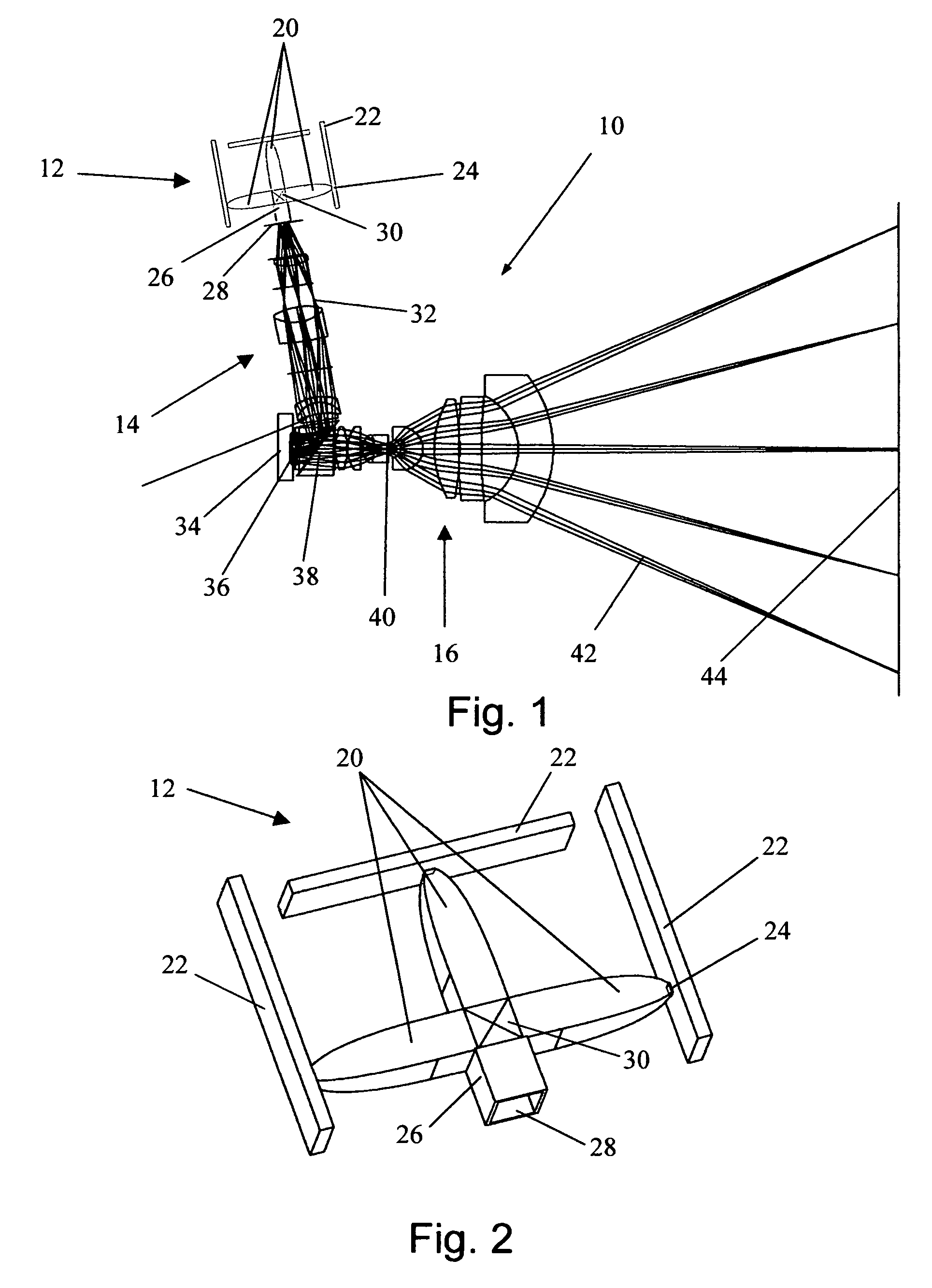
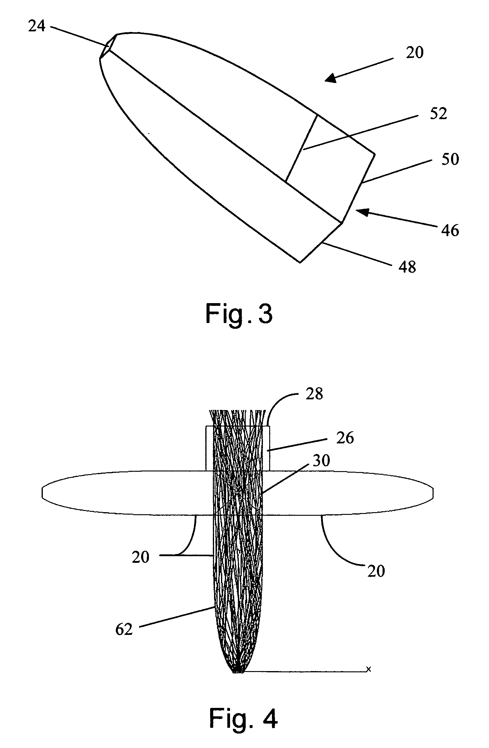
[0075]FIG. 14 shows an alternative coupling embodiment 130 of the LED projection source of FIG. 2 wherein common elements retain their original identification. Here, LED die or die arrays are attached to high thermally conductive boards 132 (typical) and coupled into input apertures 24 of CPCs 20, which can be either solid or hollow, with or without a conical input section. The output of the leftmost CPC 20 enters into a light guiding prism 138. The light is reflected through 90 degrees by the hypotenuse of 138, which is coated with a high reflectivity coating. As was the case for the prism 30 of FIG. 2, the prisms and rectangular glass sections 138, 140, 142, 143, 144, 146, 148, 134, and 136 use TIR to light pipe the light within their input dimensions so as to maintain the compact size with its inherent packaging and cost advantages. The total optical path between the exit aperture 46 of each of the three colors of LED source CPCs 20 and the output aperture 28 are substantially th...

embodiment 160

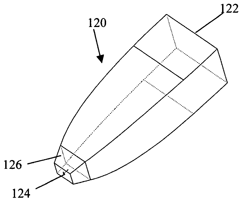
[0077]Reference is now made to FIGS. 16A and 16B which show an alternative embodiment 160 of a rectangular CPC for which the shape of the collection optic between the horizontal and vertical axes of the CPC of FIG. 3 are substantially the form of a CPC that vary continuously lengthwise (i.e. in meridonal planes passing through the surface and optical axis) from the vertical to horizontal. The points represented by 166, 168, 170, and 172 are all end points of differently shaped profiles but each of CPC form. Thus, at angles in a direction along the diagonals, passing through CPC end point 166, for example, and angles in between the horizontal and vertical CPC end points 170 and 172, represented by CPC end point 166, the form is still that of a CPC. This results in an optic that deviates from the simple rectangular cross section of the CPC of FIG. 3, that yields a substantially circular rather than rectangular far field. Thus, the compound CPCs of FIGS. 16A and 16B result in a rectang...


PUM


Abstract

The present invention generally relates to video and / or television projection systems, and more particularly, to LED based light source systems utilizing generally non-rotationally symmetric, preferably oblong or rectangular, non-imaging collection optics for providing improved projection systems relative to arc lamp and other LED based light source systems. The non-rotationally symmetric non-imaging collection optics are configured to operate with LEDs to provide preferred, generally, uniform light distributions whose étendues match those of downstream applications such as those encountered in projection systems. Also provided are various arrangements for coupling LED output to the entrance aperture of collection optics and for coupling the outputs from a plurality of collection optic outputs to form single beams of illumination of preferred patterns, intensities, and color.

Description

CROSS-REFERENCE TO RELATED APPLICATION[0001]This application claims the benefit of priority from U.S. Provisional Patent Application No. 60 / 779,556 filed on Mar. 6, 2006 in the name of Thomas J. Brukilacchio, et al. with the title LIGHT EMITTING DIODE PROJECTION SYSTEM, the entire contents of which are incorporated herein by reference.FIELD OF THE INVENTION[0002]This invention, in general, relates to projection apparatus and more particularly to the use of light emitting diodes as a source of illumination in a projection system.BACKGROUND OF THE INVENTION[0003]More powerful and brighter LED light sources are in high demand for challenging applications such as projection systems (rear and front projection televisions). Prior projection systems typically utilized short arc lamps such as high-pressure mercury, metal halide, and xenon. These lamps are capable of very high luminous emittance and are therefore suitable sources for the étendue limited projection systems and are used almost...

Claims


Application Information

Patent Timeline
Patent Type & Authority Patents(United States)
IPC IPC(8): G03B21/28F21V7/04H01L33/58H01L33/60
CPCG02B6/4298G02B27/0994G02B27/1033G02B27/1086G02B27/145G02B27/149G03B21/204H04N9/315H04N9/3152H04N9/3197G02B19/0066G02B19/0028G03B21/2033G03B21/208H01L33/58H01L33/60Y10S385/901Y10S362/80
Inventor BRUKILACCHIO, THOMAS J.DEMILO, CHARLES A.
Owner INNOVATIONS & OPTICS
Why Eureka
Try Eureka