Method for coupling terahertz pulses into a coaxial waveguide

a technology of terahertz pulses and coaxial waveguides, applied in waveguides, waveguide type devices, instruments, etc., can solve the problem of extremely low attenuation due to conductivity losses in this configuration, and achieve the effect of effective thz waveguides, efficient coupling of thz energy into waveguides, and simple geometry

Inactive Publication Date: 2015-11-03
RICE UNIV
View PDF21 Cites 141 Cited by
  • Summary
  • Abstract
  • Description
  • Claims
  • Application Information

AI Technical Summary

Benefits of technology

[0011]The present invention provides an effective THz waveguide and a method and apparatus that allow very efficient coupling of THz energy into the waveguide. The present devices are compatible with existing terahertz generation and detection techniques. In some embodiments, the invention includes the use of a coaxial antenna and a coaxial or uniaxial waveguide. Because the present invention in some embodiments uses a mode-matched detector as a mode filter to eliminate the influences of group velocity dispersion, it can provide coupling and transmission efficiencies that have not heretofore been available.
[0013]The present invention further includes a metal waveguide with very simple geometry that can be used to guide broadband THz pulses with outstanding performance, including low loss and negligible group velocity dispersion. The guided propagation of THz pulses on a metal wire behaves similarly to the transverse electromagnetic (TEM) mode of a conventional coaxial waveguide. Since the exposed surface area of a wire is much smaller than that of any previously reported metal waveguide, the attenuation due to conductivity losses is extremely low for this configuration. The efficacy and structural simplicity of the present wire waveguide present great advantages in the manipulation of guided THz radiation.

Problems solved by technology

Since the exposed surface area of a wire is much smaller than that of any previously reported metal waveguide, the attenuation due to conductivity losses is extremely low for this configuration.

Method used


Image

  • Method for coupling terahertz pulses into a coaxial waveguide
  • Method for coupling terahertz pulses into a coaxial waveguide
  • Method for coupling terahertz pulses into a coaxial waveguide

Examples


Embodiment Construction

[0035]Certain terms are used throughout the following description and claims to refer to particular system components. In the following discussion and in the claims, the terms “including” and “comprising” are used in an open-ended fashion, and thus should be interpreted to mean “including, but not limited to . . . . ”

[0036]As used herein, a waveguide is intended to refer to a device designed to confine and direct the propagation of electromagnetic waves.

Antenna

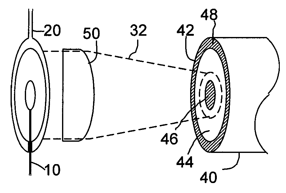
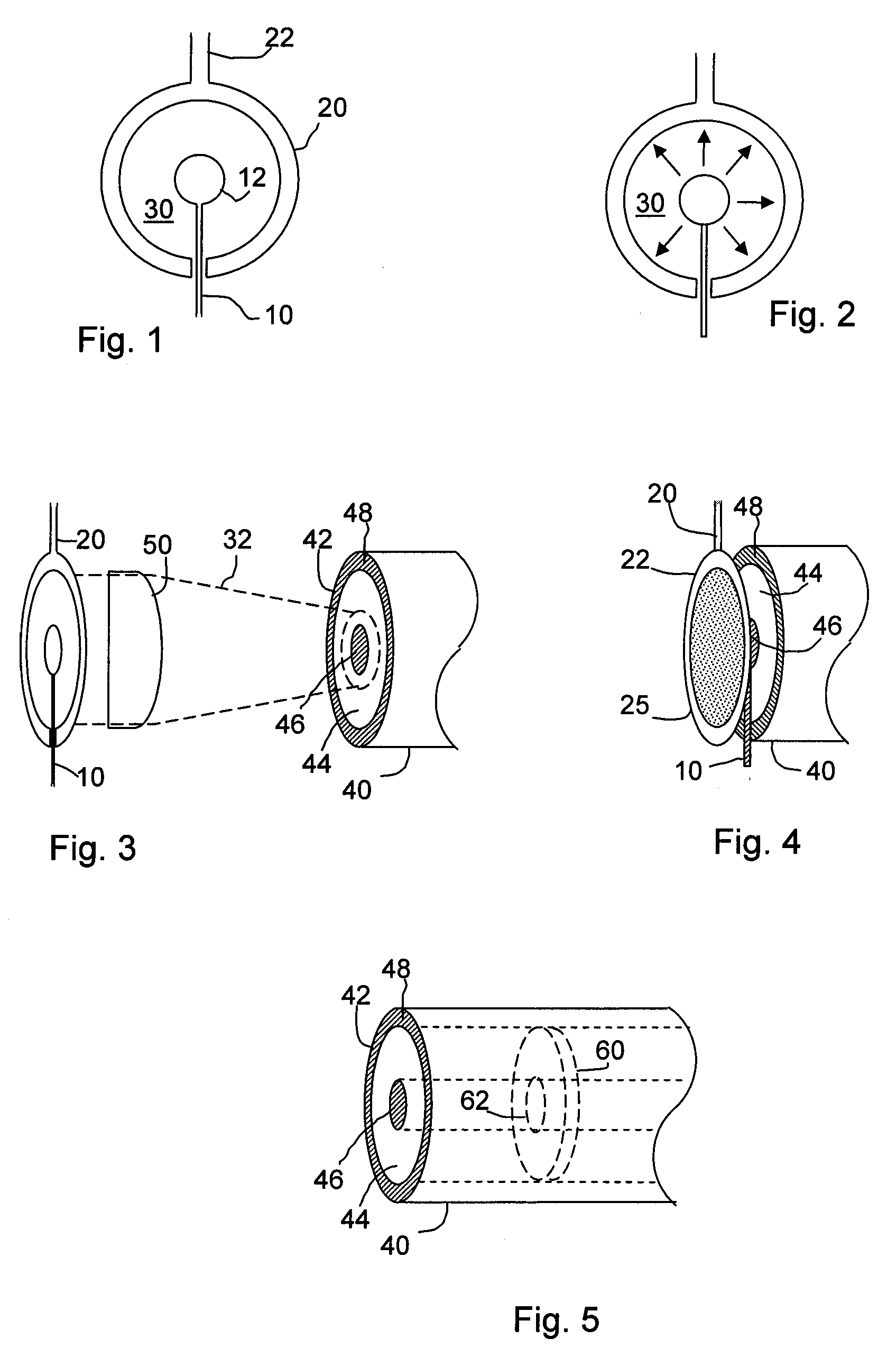
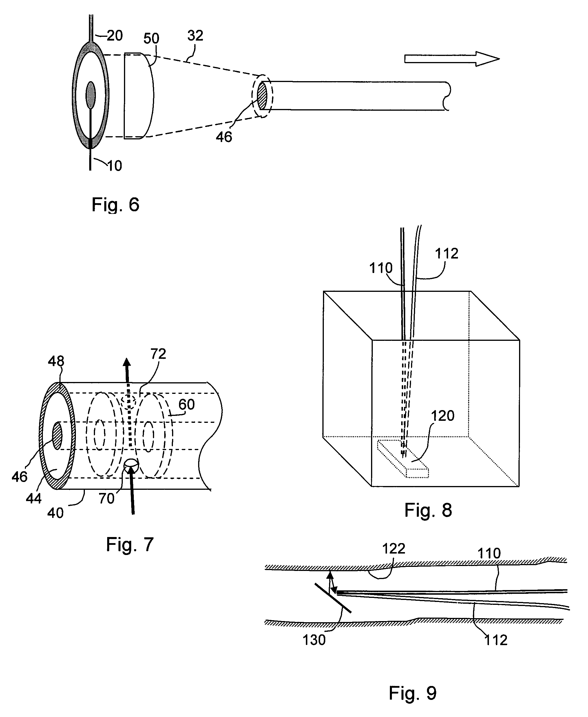
[0037]In order to efficiently couple radiation into a waveguide, it is desirable to match the spatial pattern (the mode) of the incident radiation to the mode of the waveguide. For a coaxial waveguide, this requires that the incident beam be radially polarized, since this is the characteristic of the waveguide mode with the lowest loss. Such a polarization profile is typically very difficult to generate for free-space radiation, which is why coaxial waveguides have not often been used at high frequencies. The present invention...


PUM

PropertyMeasurementUnit
diameteraaaaaaaaaa
diameteraaaaaaaaaa
diameteraaaaaaaaaa

Abstract

A system for coupling teraherz (THz) radiation to a coaxial waveguide comprises an antenna that generates THz radiation having a mode that matches the mode of the waveguide. The antenna may comprise a pair of concentric electrodes, at least one of which may be affixed to or formed by one end of the waveguide. The radiation may have wavelengths between approximately 30 μm and 3 mm. The waveguide may comprise an inner core and an outer wall defining an annular region. A terahertz sensor system may comprise a terahertz antenna comprising first and second concentric electrodes, means for generating a field across the trodes and means for triggering the emission of terahertz radiation, a first waveguide having first and second ends, said first end being coupled to said antenna so as to receive at least a portion of said terahertz radiation, and a sensor for detecting said terahertz radiation.

Description

CROSS-REFERENCE TO RELATED APPLICATIONS[0001]This application is a filing under 35 U.S.C. 371 of International Application No. PCT / US2005 / 024783 filed Jul. 13, 2005, entitled “A Method for Coupling Terahertz Pulses into a Coaxial Waveguide,” claiming priority of U.S. Provisional Patent Application No. 60 / 587,706 filed Jul. 14, 2004, which applications are incorporated by reference herein in their entirety.TECHNICAL FIELD OF THE INVENTION[0002]The present invention provides a method for guiding terahertz pulses over practical distances with low loss and low dispersion.BACKGROUND OF THE INVENTION[0003]Rapid advances in laser technology have enabled various techniques for the generation and detection of electromagnetic radiation in the terahertz region (spanning from ˜100 GHz to ˜10 THz, or wavelengths between ˜30 μm and ˜3 mm). As a result, numerous uses of terahertz radiation have been explored, including trace gas detection, medical diagnosis, security screening, and defect analysis...

Claims


Application Information

Patent Timeline
Patent Type & Authority Patents(United States)
IPC IPC(8): H01Q13/08H01P5/02G01N21/3581
CPCH01Q13/08G01N21/3581H01P5/02
Inventor MITTLEMAN, DANIEL M.WANG, KANGLIN
Owner RICE UNIV
Why Eureka
Try Eureka