Integrated Retinal Imager And Method

a retinal imager and integrated technology, applied in the field of optical monitoring techniques, can solve the problems of limitation of image quality of retinal image, loss of the majority of light, and the possibility of obtaining 1 or 2 xenon-flash-based images per second,

Active Publication Date: 2009-06-18
IBM CORP
View PDF7 Cites 125 Cited by
  • Summary
  • Abstract
  • Description
  • Claims
  • Application Information

AI Technical Summary

Benefits of technology

[0037]According to yet another broad aspect of the present invention, there is provided a method for controlling the operation of a fundus camera, the method comprising: providing predetermined exposure settings for pulse (flash) light illumination and continuous light illumination; providing data indicative of images acquired by a still image camera and a continuous mode camera; analyzing said data based on said predetermined exposure settings, and determining a new exposure settings to the pulse (flash) light control and the continuous light control, thereby enabling to utilize the continuous light measured data to predict amount of light exposure to be used in the pulse (flash) light illumination.

Problems solved by technology

Due to the limitation of current technology in fundus cameras, only 1 or 2 Xenon-flash based images per second are possible to obtain, because of limitations of the energy sources to the Flash devices.
Only laser beam based scanning devices (known also as SLO—Scanning Laser Opthalmoscopes) are able to record such events, with the limitation of smear and motion of the eye during image acquisition, causing limitation in image quality of the retina image.
However, it appears that the optical setup described in this patent suffers inter alia from losing the majority of light due to the very small acceptance angle of commercially available fibers.

Method used


Image

  • Integrated Retinal Imager And Method
  • Integrated Retinal Imager And Method
  • Integrated Retinal Imager And Method

Examples


Embodiment Construction

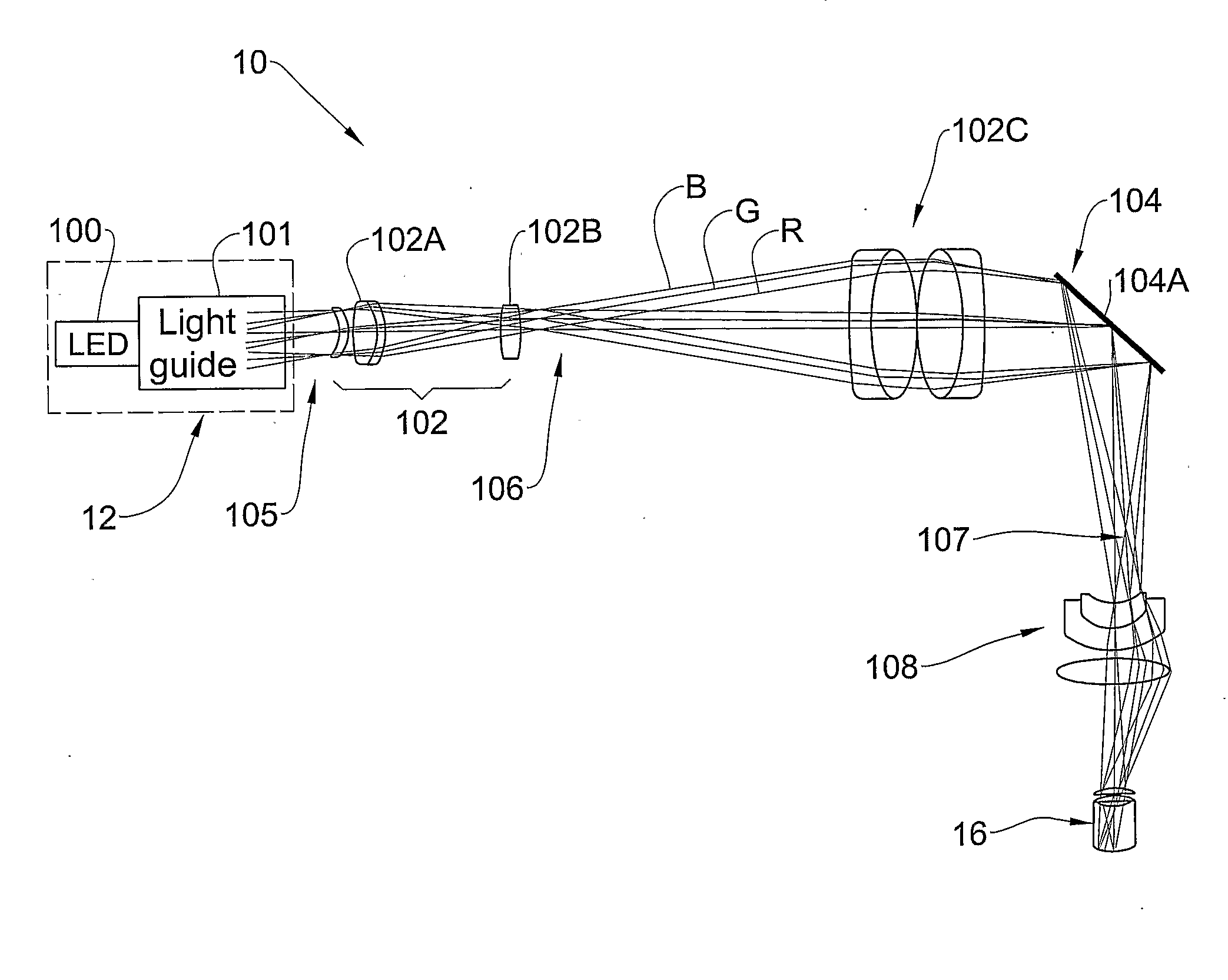
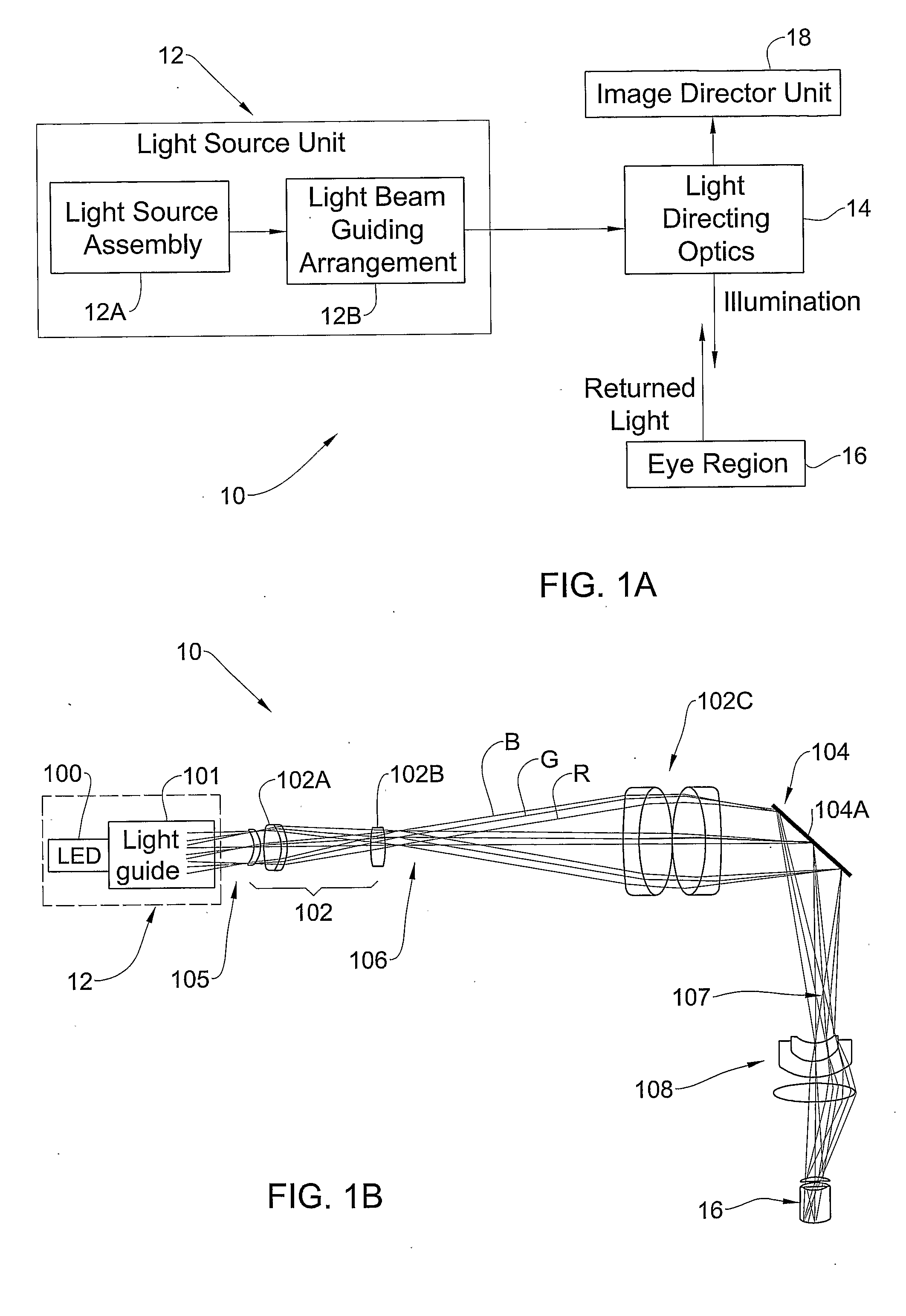
[0058]Referring to FIG. 1A there is illustrated, by way of a block diagram, the main functional elements of a system 10 of the present invention suitable to be used in a fundus camera. System 10 includes a light source unit 12, including a light source assembly 12A formed by one or more LED-based units (each including a single LED or a LED-array) and a light beam guiding arrangement 12B. Also provided in system 10 is a light directing optics 14 and an image detector 18. System 10 is associated with a control system 19 configured for controlling various operational modes of system 10 as will be described more specifically further below.

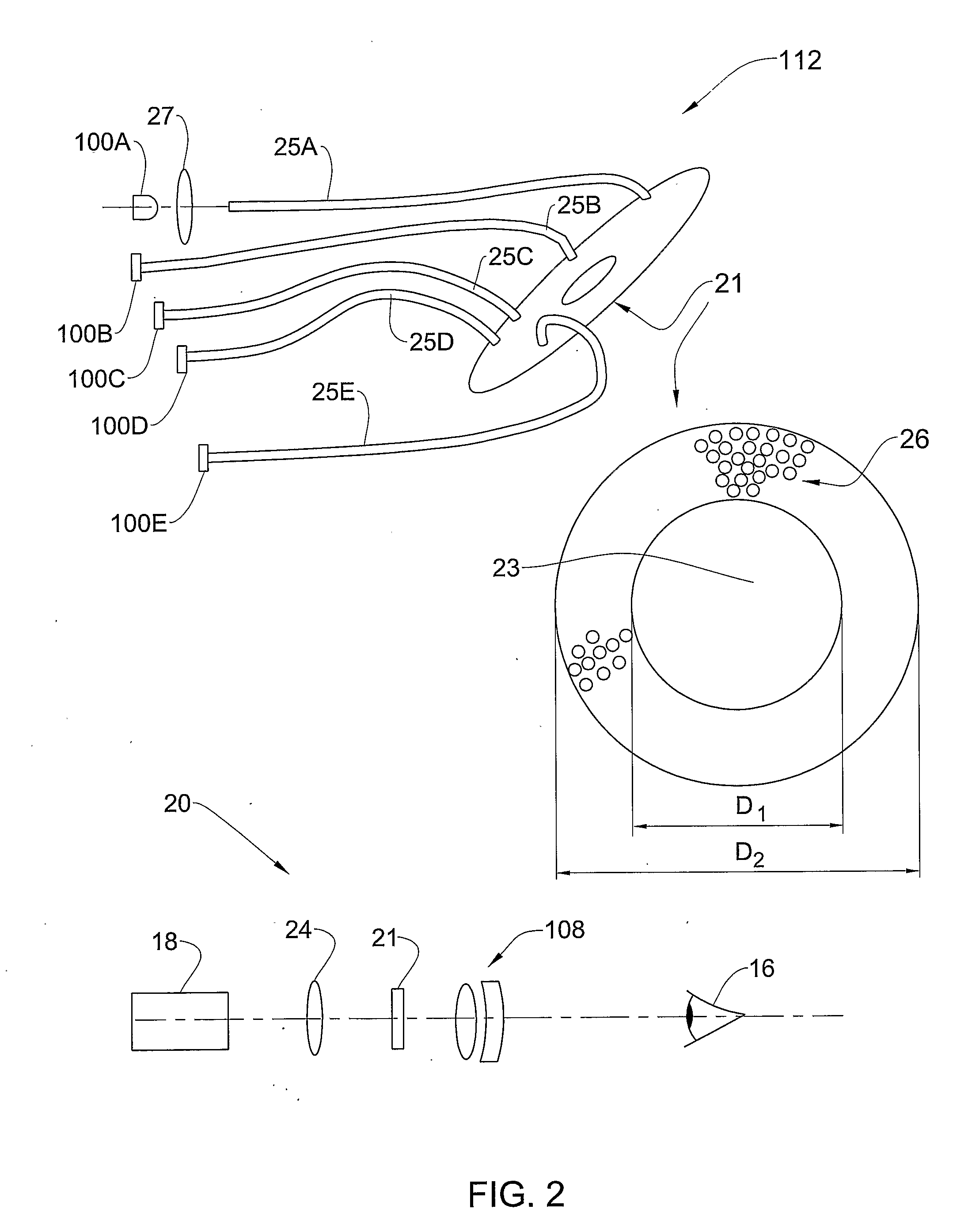
[0059]Light beam guiding arrangement 12B is configured for coupling light from the LEDs and providing output light beam(s) of a desired shape. For example, the light guiding arrangement is configured to provide a ring-like shaped light output therefrom. It should be noted that the light beam guiding arrangement may be part of the light source assembly,...


PUM


Abstract

A system and method are presented for use in imaging the patient's retina. A light source unit is provided including a light emitting diode (LED) arrangement comprising multiple LEDs of different wavelength ranges. A light guide arrangement is used with the LEDs arrangement and is configured for coupling light from the LEDs and providing output light beams of a desired shape. The illuminating light is directed towards a region on the retina, and light returned from the illuminated region is collected and directed to an image detector unit. The invention enables the use of LED light at high intensity as required in the eye retina imaging, while maintaining the required high-quality imaging. Also, the invention provides for simultaneous or quasi-simultaneous as well as high-speed imaging in FA and ICG imaging procedures, thereby satisfying a long felt need in ophthalmology. Also, the invention provides for automated illumination or light exposure control to optimize overall light exposure to the patient eye and best acquired image quality in terms of brightness, contrast and image signal-to-noise ratio.

Description

FIELD OF THE INVENTION[0001]This invention is generally in the field of optical monitoring techniques, and relates to an imaging system and method, particularly useful in ophthalmology for retinal imaging.BACKGROUND OF THE INVENTION[0002]An imager used to take pictures of the retina is known as a fundus camera. These cameras could be used in fundus (retinal) photography and fluorescence angiography procedure. The latter is a retinal examination procedure where fluorescein dye is injected into a patient vein and a fundus camera is used to record images of the retina to reveal retinal blood circulation disorders, such as leakages, hemorrhages, edema and other pathologies.[0003]Roughly speaking, there are two kinds of fundus cameras: mydriatic fundus cameras utilizing continuous illumination of the retina with visible light to permit focusing and non-mydriatic fundus cameras utilizing illumination of is the retina with invisible light, such as infrared light, which advantageously is no...

Claims


Application Information

Patent Timeline
Patent Type & Authority Applications(United States)
IPC IPC(8): A61B3/14A61B3/12F21V8/00
CPCA61B3/12
Inventor ALLON, NOAMGROSSINGER, ISRAELGOLUB, MICHAELBRIL, MOSHE
Owner IBM CORP
Why Eureka
Try Eureka