Multi-junction solar cells with a homogenizer system and coupled non-imaging light concentrator

a solar cell and homogenizer technology, applied in the field of optical concentrator systems, can solve the problems of limited utility, low solar energy flux, and low efficiency of solar cells for electrical energy production, and achieve the effect of high solar flux and efficient electrical outpu

Inactive Publication Date: 2008-02-28
RGT UNIV OF CALIFORNIA +1
View PDF26 Cites 137 Cited by
  • Summary
  • Abstract
  • Description
  • Claims
  • Application Information

AI Technical Summary

Benefits of technology

[0008] Aspects of the present invention are directed to optical devices and systems that provide extremely high solar flux onto a multi-junction solar cell, or other target cell, to produce efficient electrical output. An aplanatic optical imaging system, according to certain aspects, includes a Kohler homogenizer primary and secondary mirror subsystem that directs and concentrates illumination to a solar cell positioned proximal an exit aperture such that uniform irradiance conditions are achieved for high intensity light concentration onto the solar cell. As used herein, “aplanatic” generally refers to the condition of freedom from spherical aberration and coma. Thus, as used herein, “aplanatic optics” or “aplanatic optical system” or similar phrases generally refer to optical elements or systems that correct for, or are substantially free from, spherical aberration or coma. In certain aspects, a non-imaging light concentrator, or flux booster, is efficiently coupled to the primary and secondary mirrors.

Problems solved by technology

Solar cells for electrical energy production are very well known but have limited utility due to the very high cost of production.
For example, although substantial research has been ongoing for many years, the cost per Killowatt-hour (Kwh) still is about ten times that of conventional electric power production.
That system has a clear limitation because it produces a highly non-uniform illumination on the solar cell, which reduces the cell efficiency and system reliability.
This value cannot be tolerated by the present high-efficiency multi-junction cells, which show an abrupt drop in efficiency if they operate above 2,000-3,000 suns.
The concentration-acceptance angle product that can be attained with this configuration is very limited, because numerical aperture on the cell is small.
Additionally, the system is necessarily not compact because the optics used are refractive and includes a single Kohler integration element.

Method used


Image

  • Multi-junction solar cells with a homogenizer system and coupled non-imaging light concentrator
  • Multi-junction solar cells with a homogenizer system and coupled non-imaging light concentrator
  • Multi-junction solar cells with a homogenizer system and coupled non-imaging light concentrator

Examples


Embodiment Construction

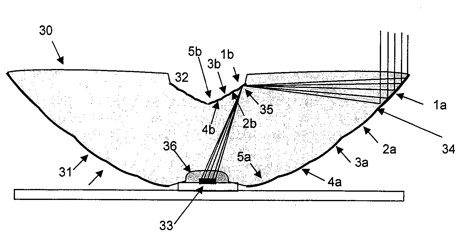
[0032] The present invention provides optical imaging systems and methods using homogenizers to concentrate and uniformly irradiate a target cell.

[0033] Aspects of the present invention make use of the inventions, including embodiments and design methods, described in U.S. Provisional Application No. 60 / 703,667 titled “Free-Form Lenticular Optical Elements and their Application to Condensers and Headlamps”, filed Jul. 28, 2005, which is incorporated herein by reference in its entirety.

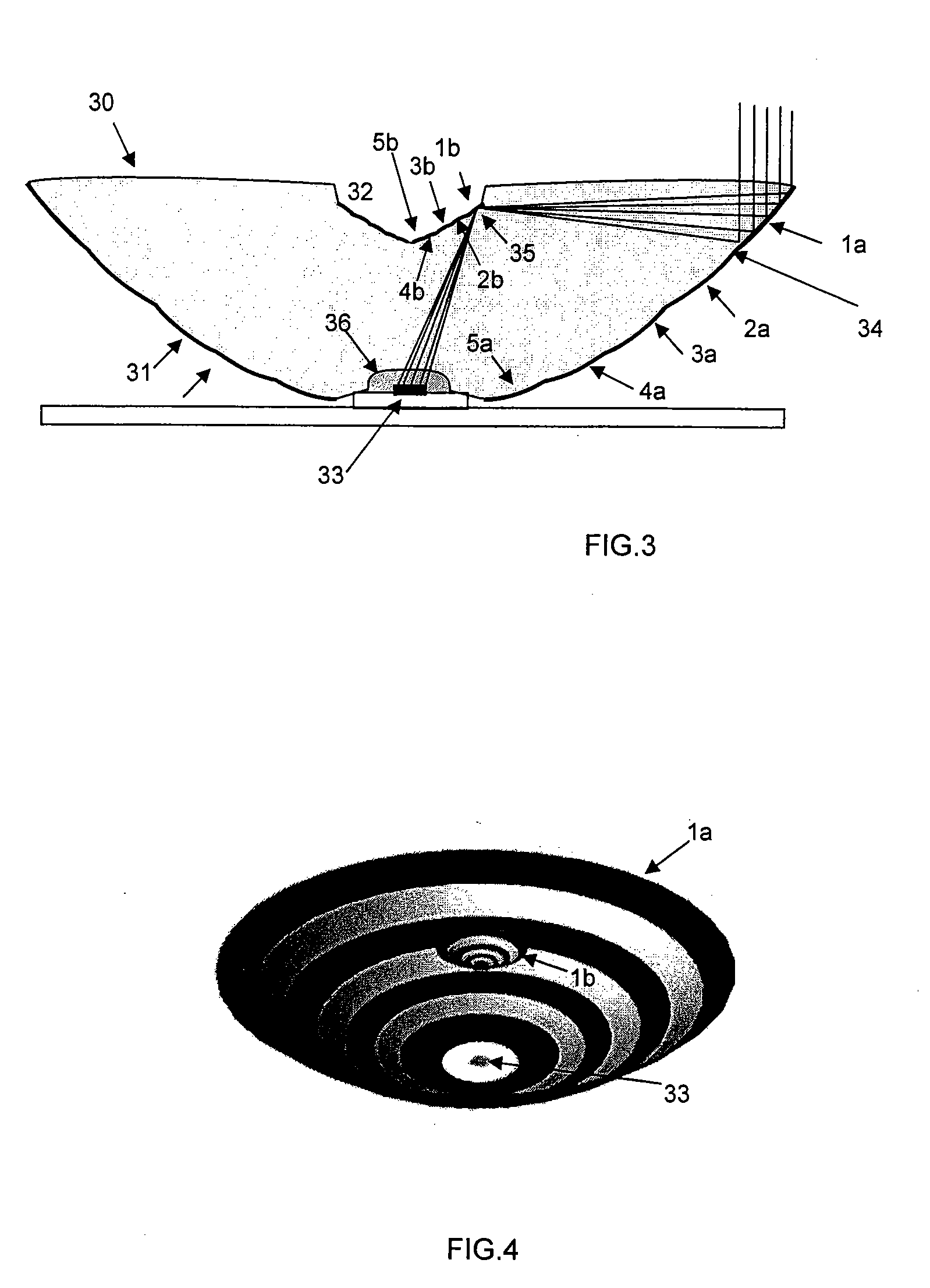
[0034] An optical system constructed in accordance with one embodiment of the invention is shown in FIG. 3. As shown, in one embodiment, a segmented secondary mirror 32 is substantially co-planar with the entrance aperture 30 of a primary mirror 31. The entrance aperture 30 and the exit aperture 36 are substantially flat. The segments on the primary 1a, 2a, etc. are essentially parabolic, with the focus of each at the associated mirror segment 1b, 2b, etc. on the secondary and vertical axis. The seco...


PUM


Abstract

Optical systems and methods that concentrate light from a distant source, such as the sun, onto a target device, such as a solar cell. Light impinging from the distant source, is focused or imaged by a plurality of primary reflective segments of a primary mirror element onto a plurality of corresponding secondary reflective segments. The secondary mirror segments image the corresponding primary segments onto an exit aperture such that the exit aperture is uniformly illuminated. A target cell may be located proximal to the exit aperture, or an entry aperture of a non-imaging concentrator may be positioned proximal the exit aperture, wherein the concentrator concentrates the reflected light onto the target cell.

Description

CROSS-REFERENCES TO RELATED APPLICATIONS [0001] This application is a continuation-in-part application of PCT application PCT / US2006 / 029464, filed Jul. 28, 2006, which claims the benefit of U.S. Provisional Application Ser. No. 60 / 703,667, filed Jul. 28, 2005 and U.S. Provisional Application Ser. No. 60 / 776,596, filed Feb. 24, 2006, the disclosures of which are incorporated herein by reference in their entirety. This application also claims the benefit of U.S. Provisional Application Ser. No. 60 / 780,520 (Attorney Docket No.18062A-009600US), filed Mar. 8, 2006, the disclosure of which is incorporated herein by reference in its entirety.BACKGROUND OF THE INVENTION [0002] The present invention relates generally to optical concentrator systems and methods utilizing solar cells for collecting the concentrated light energy, and more particularly to optical concentrator systems and methods incorporating homogenizer elements. [0003] Solar cells for electrical energy production are very well...

Claims


Application Information

Patent Timeline
Patent Type & Authority Applications(United States)
IPC IPC(8): H01L31/042G02B5/09
CPCF24J2/06F24J2/08F24J2/18G02B17/086Y02E10/44H01L31/0547G02B19/0042G02B19/0028G02B19/008H01L31/0543Y02E10/52F24S23/00F24S23/30F24S23/79F24S50/20Y02E10/47
Inventor BENITEZ, PABLOWINSTON, ROLAND
Owner RGT UNIV OF CALIFORNIA
Why Eureka
Try Eureka