
Method for vehicle classification

a vehicle and classification technology, applied in the field of vehicle classification methods, can solve the problems of affecting the classification accuracy of older vehicles, the inability to classify older vehicles without the medium attached, and the general implementation cost of systems, etc., to achieve the effect of reducing the workload and increasing the complexity of the matching process

Inactive Publication Date: 2005-12-01
WHITEGOLD SOLUTIONS
View PDF11 Cites 138 Cited by
  • Summary
  • Abstract
  • Description
  • Claims
  • Application Information

AI Technical Summary

Benefits of technology

"The present invention provides techniques for identifying and classifying vehicles based on aerial, satellite, and ground-level imagery. These techniques do not require any costly ground-based infrastructure and are flexible enough to be applied to images of vehicles taken from a wide variety of distances and angles. The techniques use a hierarchical approach to successively narrow down the classification of a vehicle to its make and model by using information about the external and internal visible edges of the vehicle. The technique also involves identifying the target vehicle's visible roof surface area and comparing it with a pre-recorded roof surface area of vehicles in a selected broad category of vehicles. The set of matching vehicles is then further narrowed down by performing wireframe matching and other corroborating and elimination tests. The invention has various applications in fields ranging from marketing to insurance and city planning."

Problems solved by technology

These systems, however, are generally very expensive to implement.
This is a very costly process if applied to all automobiles and furthermore older vehicles that do not have the medium affixed cannot be classified using this technique.
In addition, these techniques are limited to detecting vehicles at fixed locations where the ground-based infrastructure detectors are placed.
The mere detection of a vehicle, however, is of limited use.
This approach significantly reduces the workload by successively narrowing down the set of potential matching vehicles just as the complexity of the matching process increases.
For example, the errors generated during the fitting process may be compared, and the errors used to select a single matching vehicle make and model having a smallest error.

Method used


Image

  • Method for vehicle classification
  • Method for vehicle classification
  • Method for vehicle classification

Examples


Embodiment Construction

[0021] Although the following detailed description contains many specifics for the purposes of illustration, anyone of ordinary skill in the art will appreciate that many variations and alterations to the following details are within the scope of the invention. Accordingly, the following preferred embodiment of the invention is set forth without any loss of generality to, and without imposing limitations upon, the claimed invention.

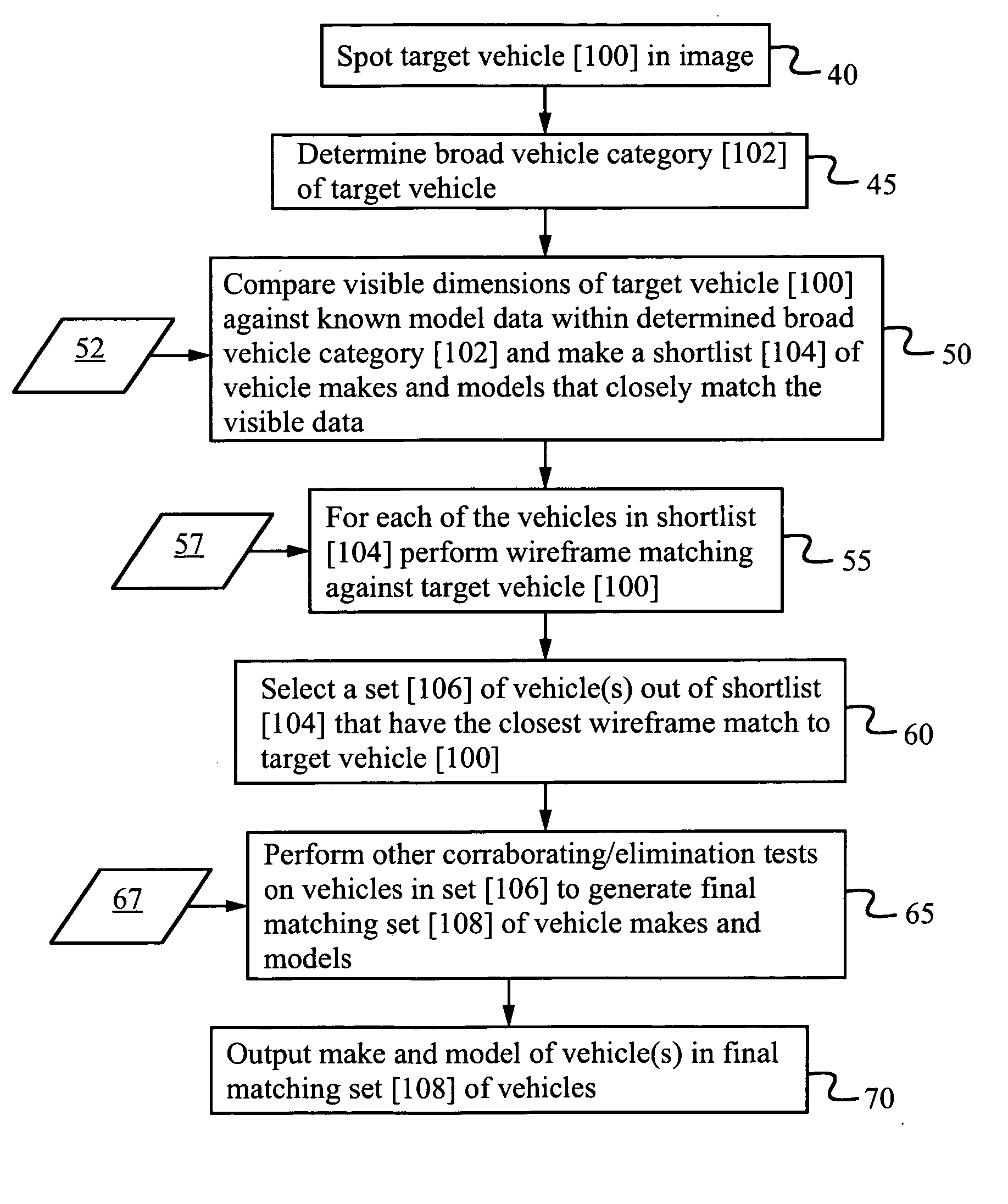
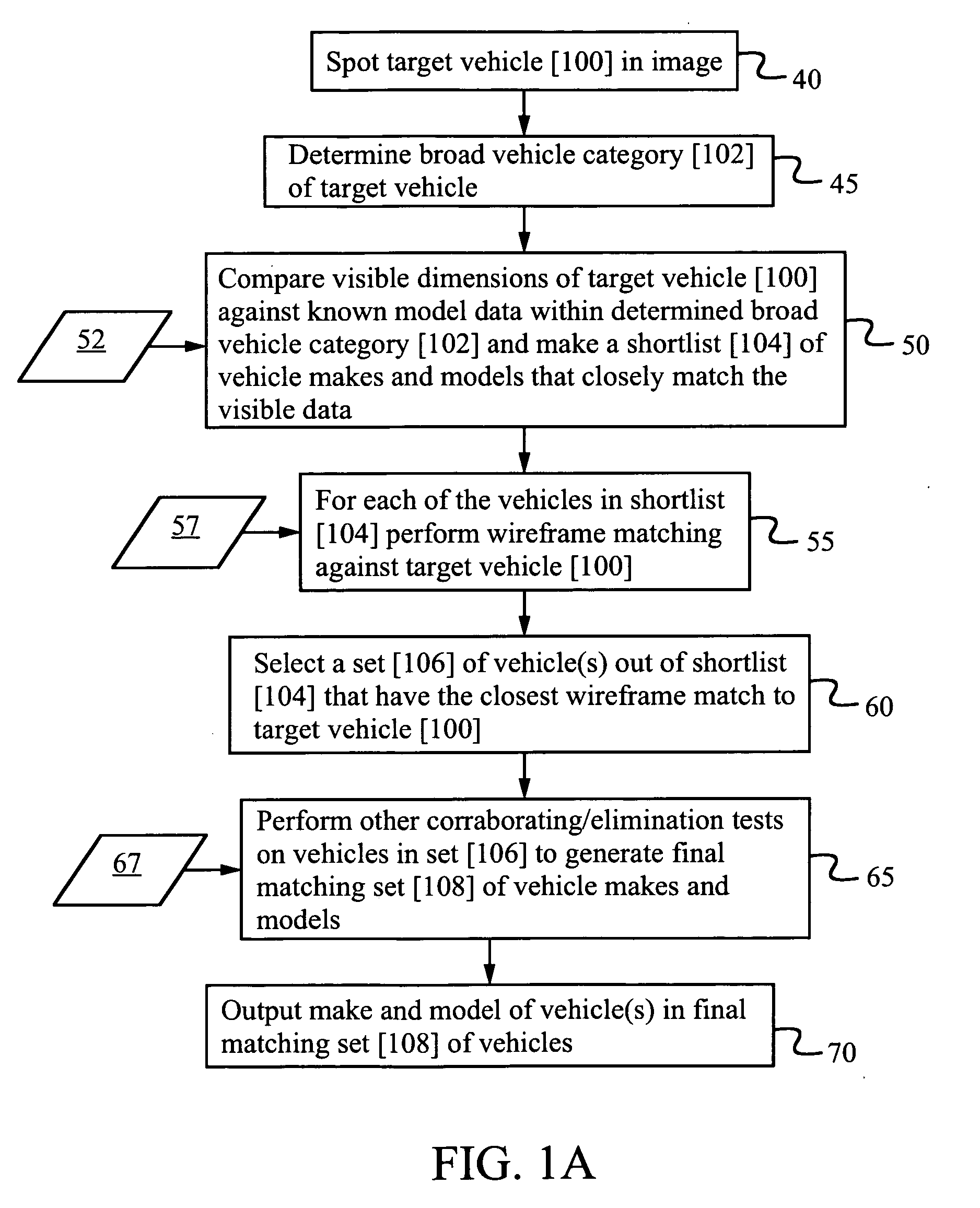
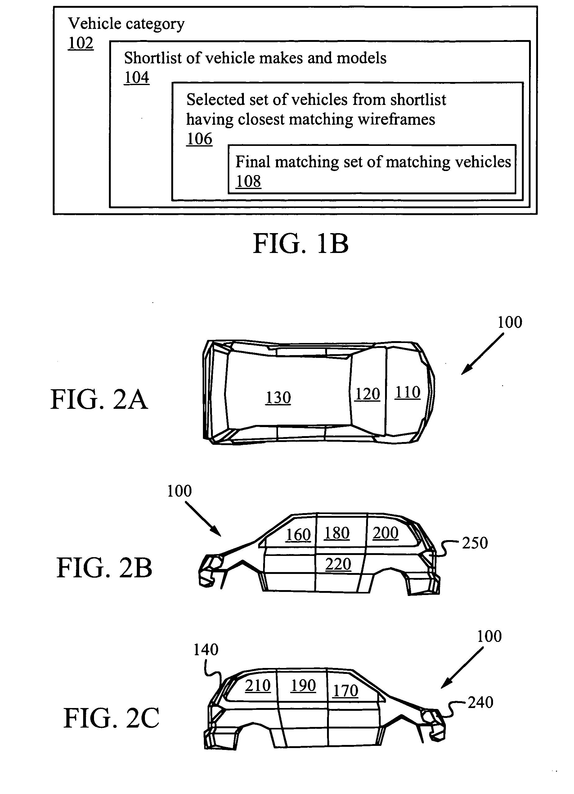
[0022]FIG. 1A shows a flowchart of a preferred embodiment of the current invention. To start the task of vehicle identification, an image is obtained. An example of an image could be an aerial image of an area, or an image of a vehicle taken at ground level. Any image where a vehicle can be seen would in general suffice to initiate the vehicle identification process. In a preferred embodiment, the image is stored in digital format on a computer-readable medium to facilitate computational image processing. In addition, subsequent steps in the method descr...


PUM


Abstract

A technique for vehicle classification and identification from images successively narrows the classification of a vehicle down to vehicle make, model, and other specific characteristics. This process uses location, size, color, shape, and other image characteristics that help differentiate vehicles from other kinds of objects in an image. A broad categorization of the target vehicle is performed by classifying the vehicle according to a predetermined set of general vehicle types. A short list is then created of potential matching vehicle makes and models within the broad category that have the best chance of matching the target vehicle. Specific visible points on the target vehicle are identified and then a wire-frame matching with pre-recorded wire-frame models of the short listed vehicles is performed to produce a set of selected vehicle makes and models.

Description

CROSS-REFERENCE TO RELATED APPLICATIONS [0001] This application claims priority from U.S. Provisional Patent Application 60 / 568410 filed May 4, 2004 which is incorporated herein by reference.FIELD OF THE INVENTION [0002] This invention relates generally to methods for classification of vehicles using aerial, satellite, or ground-based imagery. BACKGROUND ART [0003] Current state of the art in vehicle classification mostly relates to classification of vehicles using a ground-based infrastructure. Such infrastructure includes inductor sensors, weight sensors, ultrasonic sensors, interrogator-transponder systems, and RF identity transmitters and receivers. These systems, however, are generally very expensive to implement. Some vehicle classification techniques described in the literature require affixing items to vehicles. Examples of such items include holographic media and infrared radiation sensitive identification media inserted between windshield layers. This is a very costly proc...

Claims


Application Information

Patent Timeline
Patent Type & Authority Applications(United States)
IPC IPC(8): G06F17/00G06V20/13
CPCG06K9/00208G06K2209/23G06K9/0063G06V20/647G06V20/13G06V2201/08
Inventor DEVDHAR, PRASHANT P.
Owner WHITEGOLD SOLUTIONS
Learn More