Power supply with dimming control for high-power DC LED lamp

a technology of dimming control and led lamps, which is applied in the direction of instruments, light sources, electroluminescent light sources, etc., can solve the problems of reducing the service life of the lamp, increasing the burden on the power supply, and the conventional means of dimming control by changing the voltage or current are inadequate for the light-emitting unit of the high-power dc. achieve the effect of enhancing the practicability and power-saving efficiency of the high-power dc led

Inactive Publication Date: 2013-02-12
ABLECOM TECH
View PDF5 Cites 0 Cited by
  • Summary
  • Abstract
  • Description
  • Claims
  • Application Information

AI Technical Summary

Benefits of technology

[0007]For improving the traditional high-power DC LED lamp whose power transformer lacks for dimming control, the inventor of the present invention invited a power supply with dimming control for a high-power DC LED lamp, with the attempt to adjust luminance (brightness) and power consumption (consumed watts) of a light-emitting unit in the high-power DC LED lamp, so as to enhance the practicability and power-saving efficiency of the high-power DC LED lamp. The power supply is characterized in integrating a driver 2, a transformer, and an adapter or a power supply 1 in the high-power DC LED lamp 4 into a whole. The power supply is further provided with a variable resistor 3 for adjusting electric current. Thereby, the power supply is capable of dimming light-emitting unit(s) 41 of one set or more sets of high-power DC LED lamps 4.

Problems solved by technology

However, to a lamp with a high-power DC LED unit 41, by changing the voltage or current at the input end of its driver 2 is not effective to get significant dimming effects (only a variation about 10%-20%), and doing so can bring additional burdens to the power supply of the high-power DC LED lamp, leading to decreased stability and service life of the lamp.
This is because the driver 2 typically provided in such a high-power DC LED lamp offsets the change of the voltage or current made at the input end of the driver 2, so the conventional means for dimming control by changing the voltage or current is inadequate for the light-emitting unit of a high-power DC LED lamp.
In the current technology, there is no way to perform dimming control of the high-power DC LED unit 41 of a high-power DC LED lamp by adjusting a transformer, an adapter / power supply 1, a driver 2 in the burner / bulb or a conventional dimmer.
Therefore, the existing high-power DC LED lamp 4 fails to have dimming control and can be only operated between “on” and “off” and the lack of dimming control weakens the practicability of the existing device.

Method used


Image

  • Power supply with dimming control for high-power DC LED lamp
  • Power supply with dimming control for high-power DC LED lamp
  • Power supply with dimming control for high-power DC LED lamp

Examples


Embodiment Construction

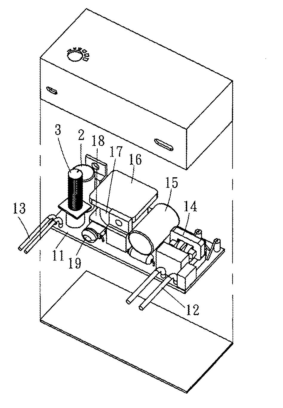
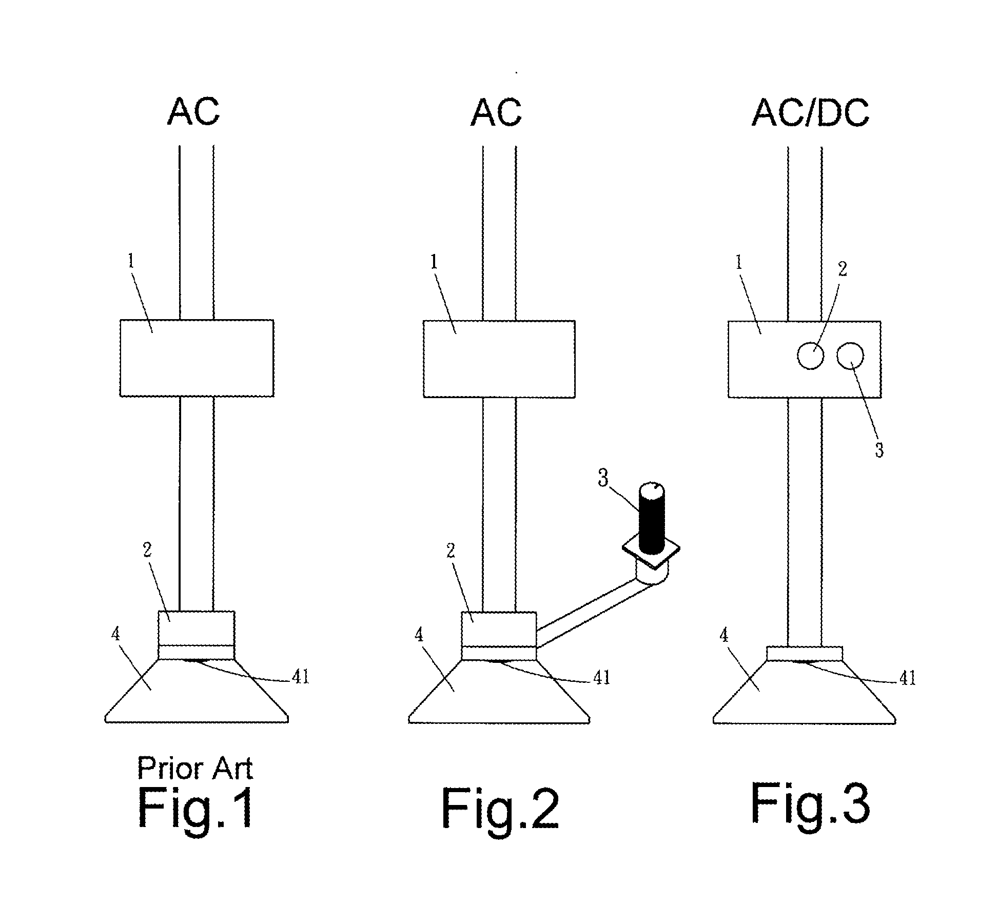
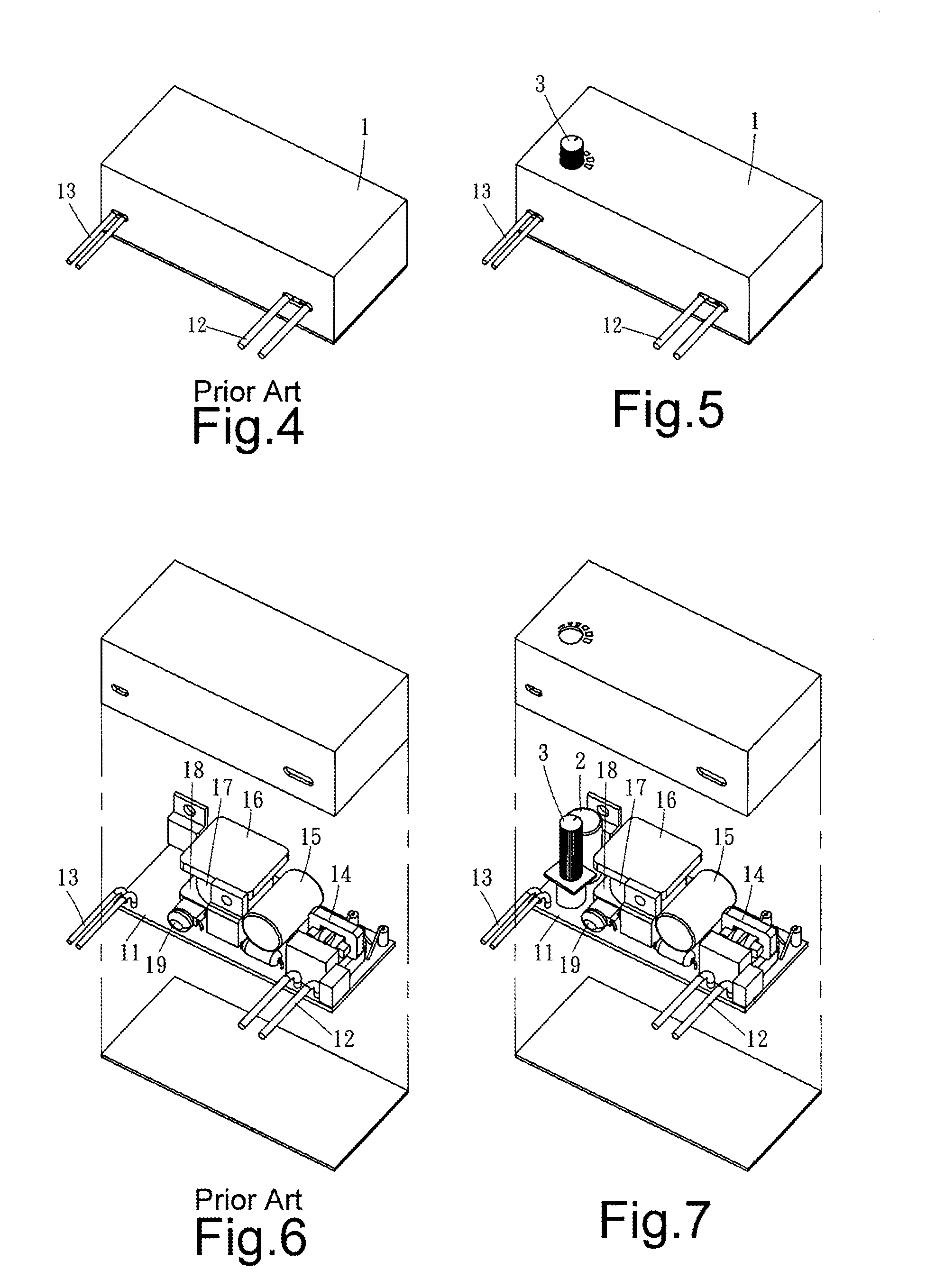
[0018]Referring to FIGS. 1, 2, 3, 5, 7 and 9, a power supply with dimming control for a high-power DC LED lamp of the present invention is primarily configured as below. Between a power input end 12 and a power output end 13 on a circuit board 11 of a normal transformer, adapter or power supply 1, in addition to an inductance loop 14, a capacitor element 15, a filter element 16, a pulse width modulator 17, an overload protection circuit 18 and a feedback control circuit 19 as usually provided, there is specially a variable resistor 3 between the power input end 12 and the power output end 13 on the circuit board 11.

[0019]The above configuration serves to adjust an input high voltage (about 90˜264V) or low voltage (about 3˜48V) into any of the voltage values of 3.5V, 7V, 10.5V, 13.5V, 17.5V, 21V, 25V, 28V, 31.5V, 35V, 38.5V, 42V and higher according to the need of the high-power DC LED, and then the specially provided variable resistor 3 changes a current for the use of the high-powe...


PUM


Abstract

A power supply with dimming control for a high-power DC LED lamp is provided. Particularly, a variable resistor is provided to a circuit of the high-power DC LED lamp for changing a current supplied to a light-emitting unit of the high-power DC LED lamp, thereby adjusting luminance (brightness) and power consumption (consumed watts) of the high-power DC LED unit of the high-power DC LED lamp. The variable resistor is provided to a driver, transformer, adaptor or power supply of the high-power DC LED lamp in a built-in manner or a remotely connected manner.

Description

BACKGROUND OF THE INVENTION[0001]1. Technical Field[0002]The present invention relates to a power supply with dimming control for high-power DC LED lamps. More particularly, the power supply is capable of adjusting luminance (brightness) and power consumption (consumed watts) of a light-emitting unit in a conventional high-power DC LED lamp, and is applicable to dimming control of one or more sets of such high-power DC LED units.[0003]2. Description of Related Art[0004]Referring to FIG. 1, FIG. 4, FIG. 6 and FIG. 8, in the case of average halogen lamps and tungsten filament lamps (incandescent lamps), the dimming control is achieved by changing the voltage or current of a transformer 1 in the lamp. However, to a lamp with a high-power DC LED unit 41, by changing the voltage or current at the input end of its driver 2 is not effective to get significant dimming effects (only a variation about 10%-20%), and doing so can bring additional burdens to the power supply of the high-power DC...

Claims


Application Information

Patent Timeline
Patent Type & Authority Patents(United States)
IPC IPC(8): G05F1/00H05B39/04H05B37/02H05B41/36
CPCH05B33/0803H05B33/0809H05B45/00H05B45/10
Inventor LIANG, CHIEN KUO
Owner ABLECOM TECH
Why Eureka
Try Eureka