Display apparatus

a technology of display panel and display screen, which is applied in the direction of color television details, picture reproducers using projection devices, instruments, etc., can solve the problems of interference stripes, spherical aberration and chromatic aberration, and less viewable area on the display panel, so as to reduce the size of non-light emitting areas and increase the display area

Active Publication Date: 2013-02-19
AU OPTRONICS CORP
View PDF15 Cites 0 Cited by
  • Summary
  • Abstract
  • Description
  • Claims
  • Application Information

AI Technical Summary

Benefits of technology

[0007]Hence, an aspect of the present invention is to provide a display apparatus for magnifying the display area on a display panel; reducing the size of non-light emitting area on the display panel; and reducing the occurrence of Moire stripes, darker and lighter stripes and image ghosting problems.
[0008]Another aspect of the present invention is to provide a display apparatus for promoting the resolution uniformity of the display panel and increasing the slant angle allowed for viewing the display panel.
[0011]With the application of the aforementioned display apparatus, the size of non-light emitting area on a display panel can be reduced; the thickness and weight can reduced by using a Fresnel lens, and the occurrence of interference stripes can be reduced via a planar portion located at a central portion of the lens; and the Fresnel lens with variating focus lengths and the pixel groups having non-periodically variating widths are used together to promote the resolution uniformity of the display panel and increase the slant angle allowed for viewing the display panel.

Problems solved by technology

In the process for manufacturing a liquid crystal display (LCD), due to the causes from a panel circuit wiring layout, a mold frame and cutting tolerances, the frame border area located at four surrounding edges of a LCD panel cannot display any image, and thus an irremovable border area with non-light emitted is formed around the display panel, resulting in less viewable area on the display panel.
However, the conventional skill using the magnifying lens may cause sever spherical aberration and chromatic aberration, and the lens itself is quite heavy and thick, and thus is disadvantageous to the application of portable display emphasizing the features of lightness and thinness.
As to the conventional skill using the circular Fresnel lens, although it may be able to reduce the thickness and weight of the lens, yet the periodical structure of the Fresnel lens may interfere with the pixels area on the LCD panel to cause interference stripes, such as Moire patterns, etc.
Particularly, when being viewed with a large slant view angle, the image shown on the LCD panel is further affected by an overlarge facet angle or slope angle of a micro-prism structure on the circular Fresnel lens, and darker and lighter stripes or ghosting phenomena are generated thereby, thus resulting in visual defects.

Method used


Image

  • Display apparatus
  • Display apparatus
  • Display apparatus

Examples


Embodiment Construction

[0019]Reference will now be made in detail to the present preferred embodiments of the invention, examples of which are illustrated in the accompanying drawings. Wherever possible, the same reference numbers are used in the drawings and the description to refer to the same or like parts.

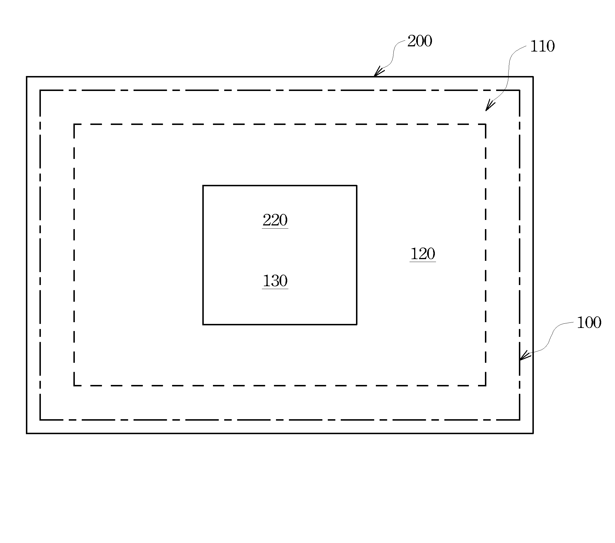
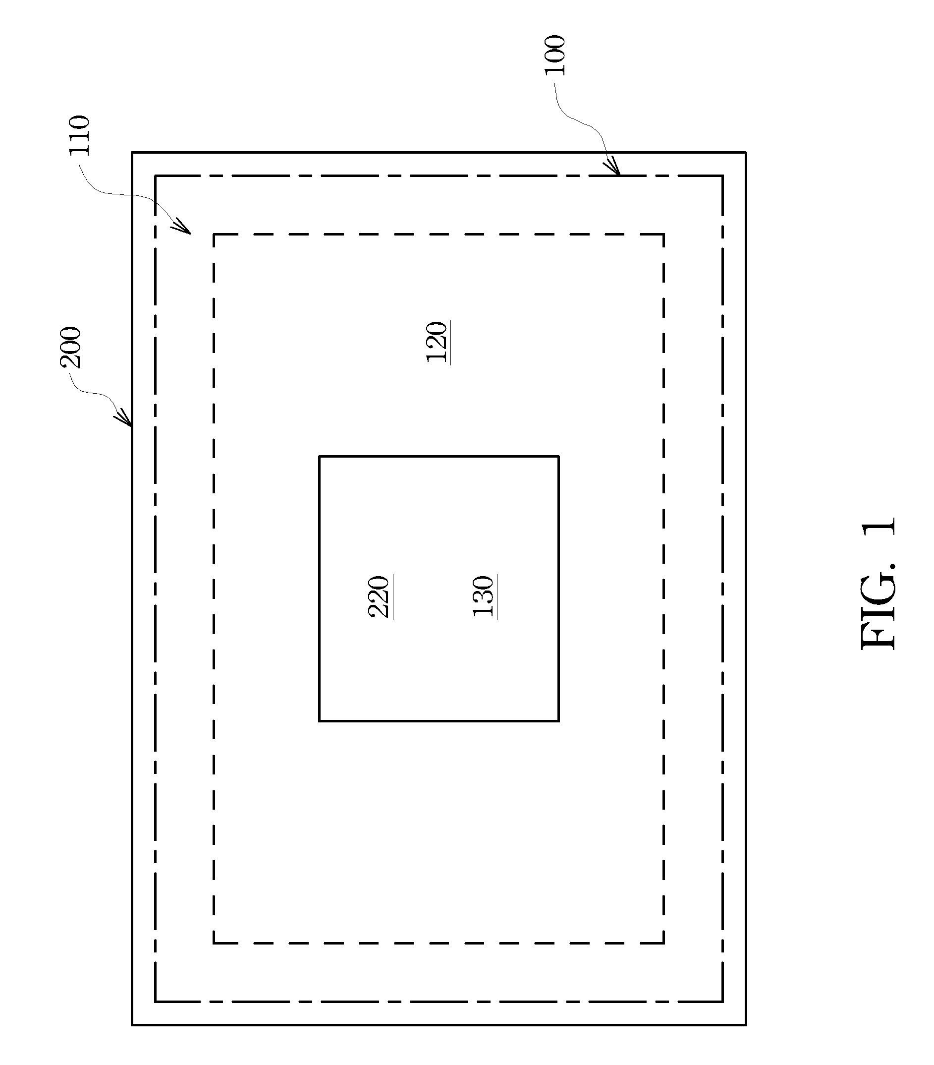
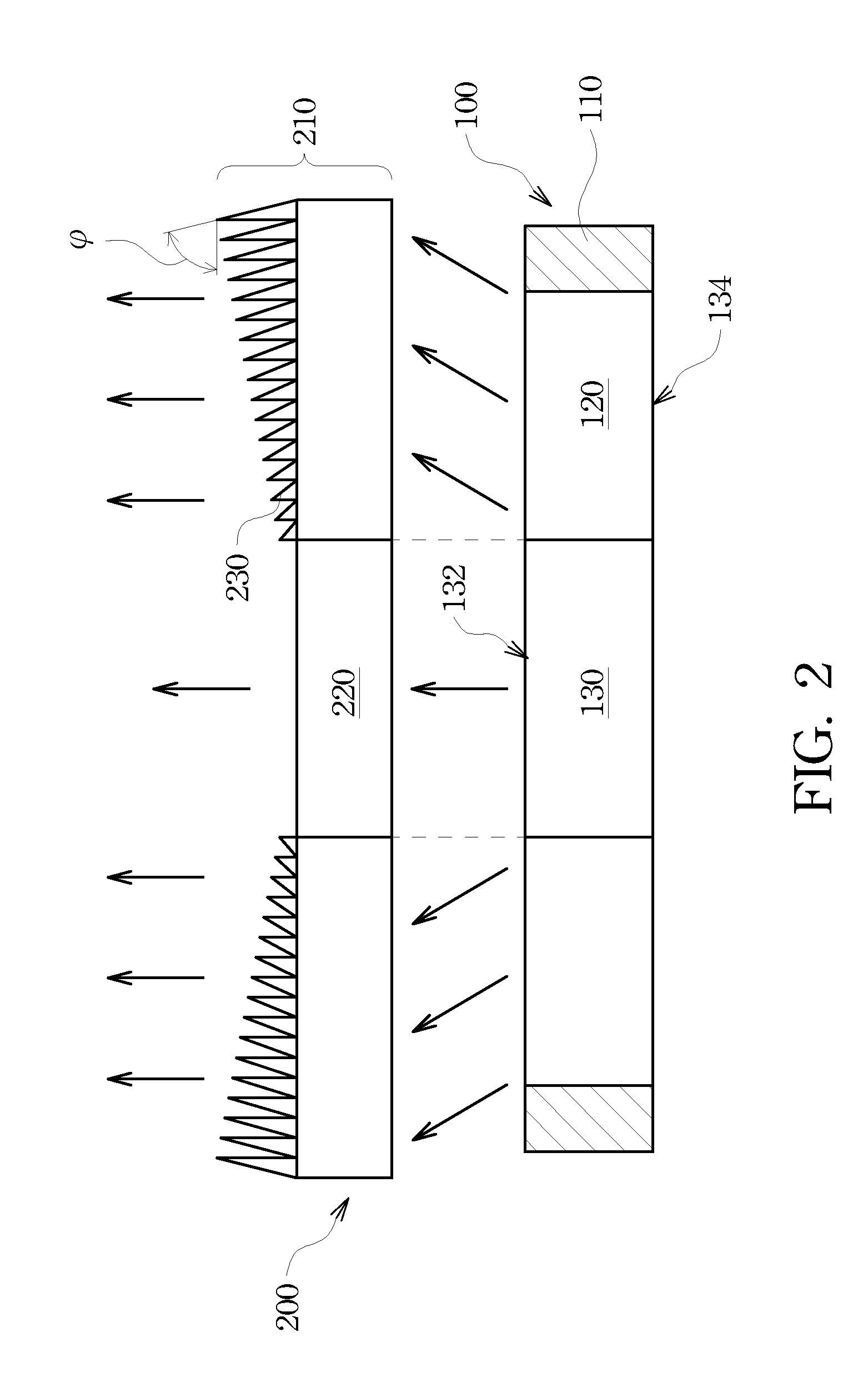
[0020]Referring to FIG. 1 and FIG. 2, FIG. 1 and FIG. 2 are schematic top and exploded front views of a display apparatus according to an embodiment of the present invention. The display apparatus of this embodiment comprises a lens 200 and a display panel 100, wherein the area of the lens 200 is greater than or equals to that of the display panel 100, and the lens 200 shields the entire surface of the display panel 100. On the display panel 100, a width-fixed pixel zone 130, a width-variating pixel zone 120 and a border zone 110 are arranged sequentially from its center to its edges, wherein the border zone 110 is a non-light emitting area, and the width-fixed pixel zone 130 and the width-variating ...


PUM


Abstract

A display apparatus is disclosed, and comprises a display panel and a lens. On the display panel, there are a width-fixed pixel zone, a width-variating pixel zone and a border zone arranged sequentially from the center to the edges of the display panel, wherein there are a plurality of width-fixed pixels disposed in the width-fixed zone, and there are a plurality of width-variating pixel groups disposed in the width-variating pixel zone, and the widths of the width-variating pixel groups are present in a first decreasing sequence. The lens has a focus-length-variating portion and a planar portion, wherein the planar portion is aligned with the width-fixed pixel zone, and the focus-length-variating portion is disposed to correspond to the border zone and the width-variating pixel zone. The focus lengths of the focus-length-variating portion corresponding to the width-variating pixel groups are present in a second decreasing sequence.

Description

RELATED APPLICATIONS[0001]This application claims priority to Taiwan Application Serial Number 97142072, filed Oct. 31, 2008, which is herein incorporated by reference.BACKGROUND[0002]1. Field of Invention[0003]The present invention relates to a display apparatus. More particularly, the present invention relates to a display apparatus comprising a lens with variating focus lengths and a display panel with pixels having non-periodically variating widths.[0004]2. Description of Related Art[0005]In the process for manufacturing a liquid crystal display (LCD), due to the causes from a panel circuit wiring layout, a mold frame and cutting tolerances, the frame border area located at four surrounding edges of a LCD panel cannot display any image, and thus an irremovable border area with non-light emitted is formed around the display panel, resulting in less viewable area on the display panel. In order to reduce the border area with non-light emitted for magnifying the viewable area on the...

Claims


Application Information

Patent Timeline
Patent Type & Authority Patents(United States)
IPC IPC(8): G09G3/36
CPCG02F1/133526
Inventor KAO, KUO-FENGCHEN, ZENG-DECHENG, TSUNG-CHINHWU, KEH-LONGCHOU, WENG-BINGLEE, SEOK-LYUL
Owner AU OPTRONICS CORP
Why Eureka
Try Eureka