Upright steam mop sweeper

a steam mop and sweeper technology, applied in the field of upright bare floor cleaners, can solve the problems of difficult to transfer the entire debris pile, inconvenient movement, and even pain for some users, and achieve the effects of reducing the number of users, and improving the cleaning

Active Publication Date: 2013-06-11
BISSELL INC
View PDF22 Cites 65 Cited by
  • Summary
  • Abstract
  • Description
  • Claims
  • Application Information

AI Technical Summary

Benefits of technology

[0017]In another embodiment, the dirt receptacle is slidably received within the chamber and is installed into the base housing through the opening. Further, a latch in the base housing is included for releasably retaining the dirt receptacle within the base housing. In this embodiment, the dirt receptacle has a peripheral flange and the mop cloth is removably attached to the flange. The dirt receptacle is mounted to the mop pad so that the mop pad can be removed from the base simultaneously with the dirt receptacle.

Problems solved by technology

However, the broom and dustpan are not ideal for removing dry particles because it is difficult to transfer the entire debris pile into the dustpan.
Such motion can be inconvenient, difficult, and even painful for some users.
Dust cloths can also be used, but large dirt particles do not sufficiently adhere thereto.
Another option is vacuuming the dry debris, but most homes are equipped with vacuum cleaners that are designed for use on carpets and can damage bare surfaces and offer marginal cleaning performance on bare floor surfaces.
Each time more cleaning solution is required, the mop is usually placed in the same bucket, and after several repetitions the cleaning solution becomes dirty and cold.
Mops generally require use of chemicals which can be problematic for users that have allergies or other sensitivities to cleaning chemicals, fragrances, etc.
The end result tends to be a wet floor that is coated with soap residue upon drying.
Furthermore, movement of the mop requires physical exertion, and the mop head wears with use and must be replaced periodically.
Additionally, cloths are not as absorbent as mops and, therefore, can leave excessive soiled cleaning solution on the floor.
Other devices are capable of performing all functions without accessories, but have complex designs and features that can be difficult and confusing to operate.
Further, upon completion of a cleaning task a mixture of soiled cleaning solution and dirt remains in the recovery tank forming sludge that is undesirable to dispose in the trash or down a sink drain.
Because the steam is airborne, it may be undesirable to include detergents and the like in the cleaning solution.
However, the steam cleaning systems can suffer from poor cleaning performance.
Additionally, the high power required for generating steam does not allow ample remaining power for running a vacuum motor, so cleaning performance is further hindered.
Overall power consumption presents a major hurdle in North America and other 120V markets when contemplating the combination of steaming and vacuum cleaning functions.
Accordingly, it becomes extremely difficult to combine effective vacuum cleaning function with a simultaneous steaming function without running the risk of tripping residential circuit breakers.
However, it still requires two cleaning steps—namely, sweeping or vacuuming dry debris followed by steam mopping.

Method used


Image

  • Upright steam mop sweeper
  • Upright steam mop sweeper
  • Upright steam mop sweeper

Examples


Embodiment Construction

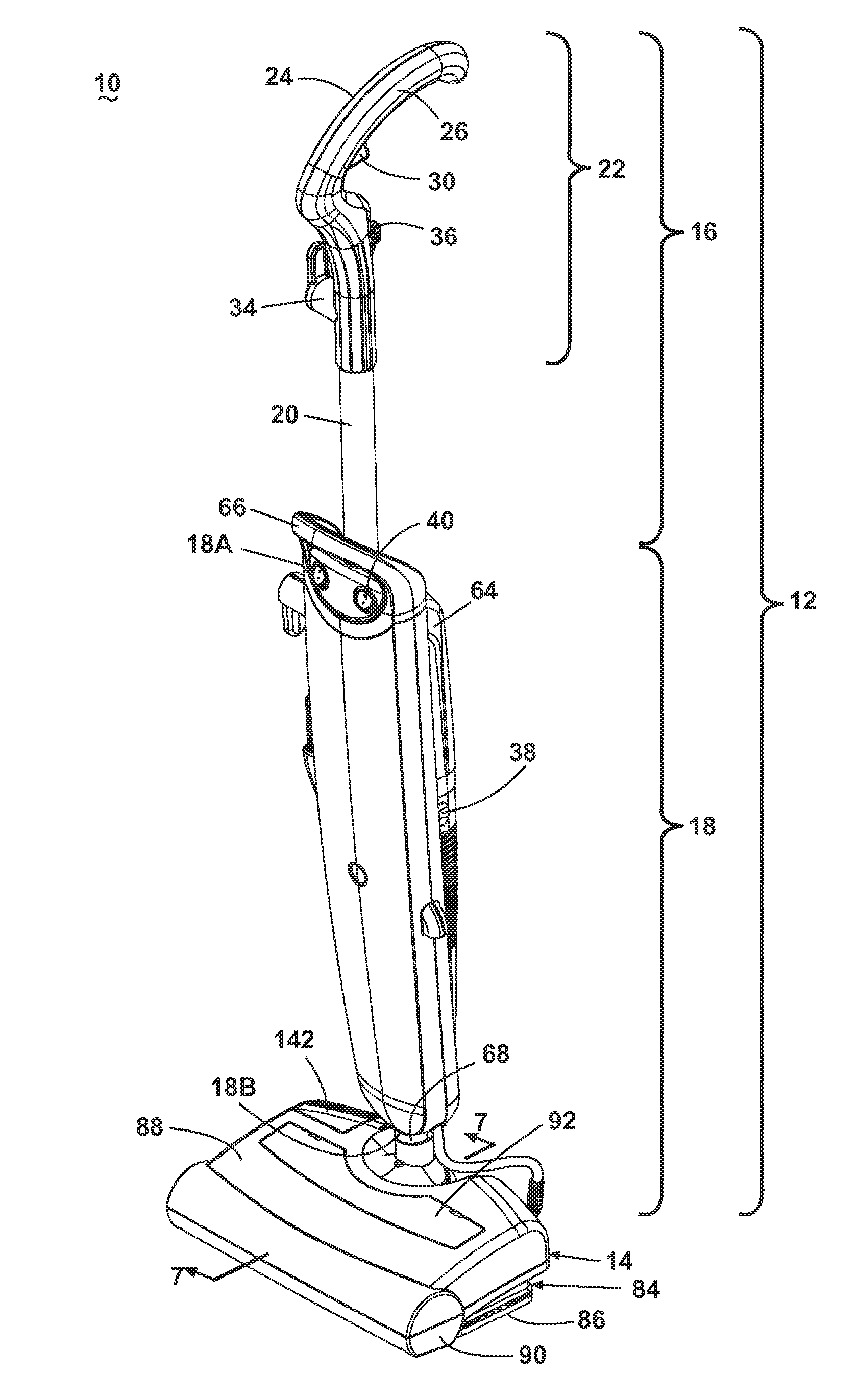
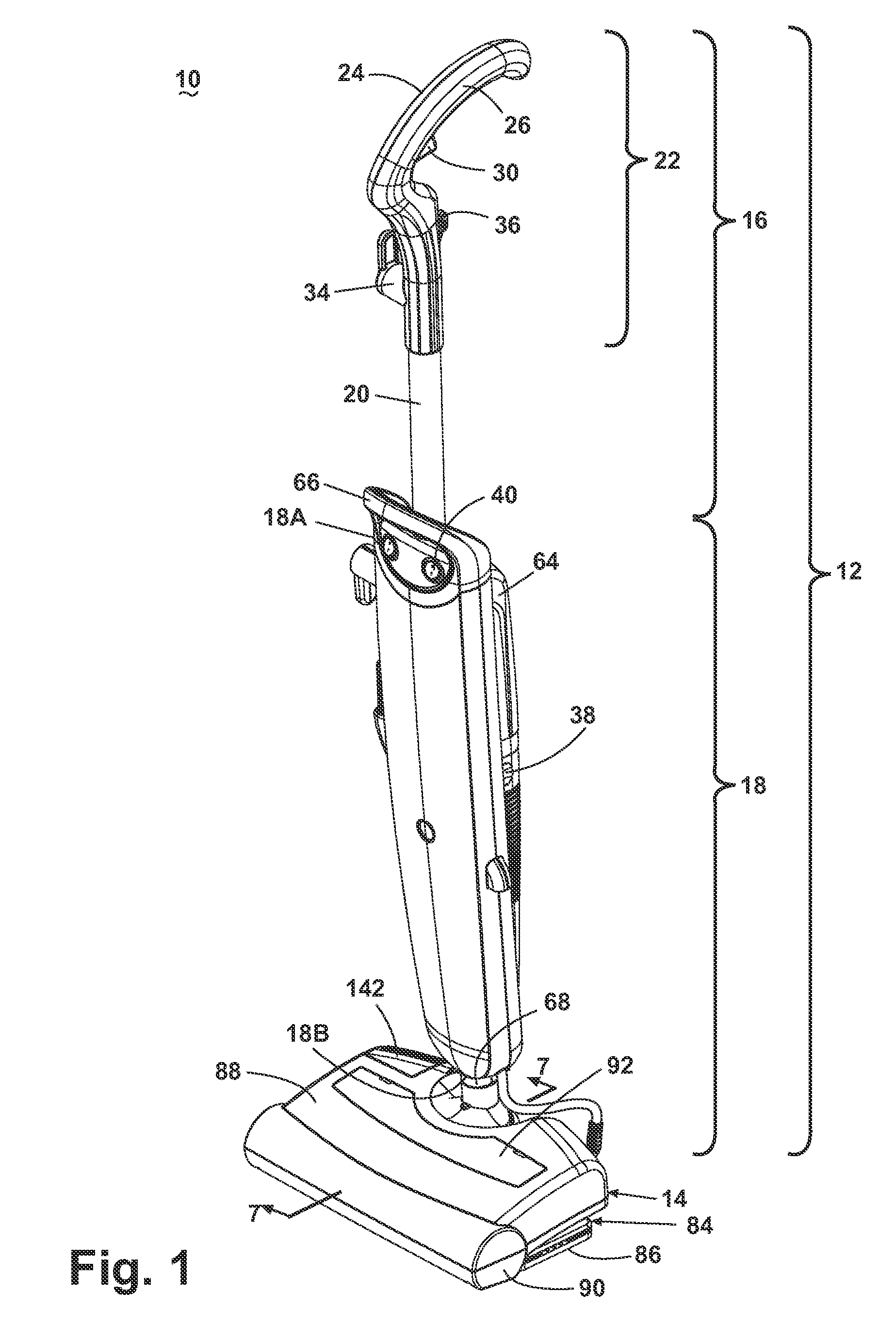
[0050]Referring now to the drawings and to FIGS. 1 and 2 in particular, a steam mop sweeper 10 according to the invention comprises an upright handle assembly 12 pivotally mounted to a foot or base assembly 14. The handle assembly 12 can pivot from an upright or vertical position, where the handle assembly 12 is substantially vertical relative to a surface to be cleaned, to a lowered position, whereby the handle assembly 12 is respectively moved in a rearward direction relative to the base assembly 14 and is angled relative to the surface to be cleaned. The steam mop sweeper 10 does not incorporate traditional wheels associated with vacuums; instead, the steam mop sweeper 10 is adapted to glide across the surface on a mop cloth 86.

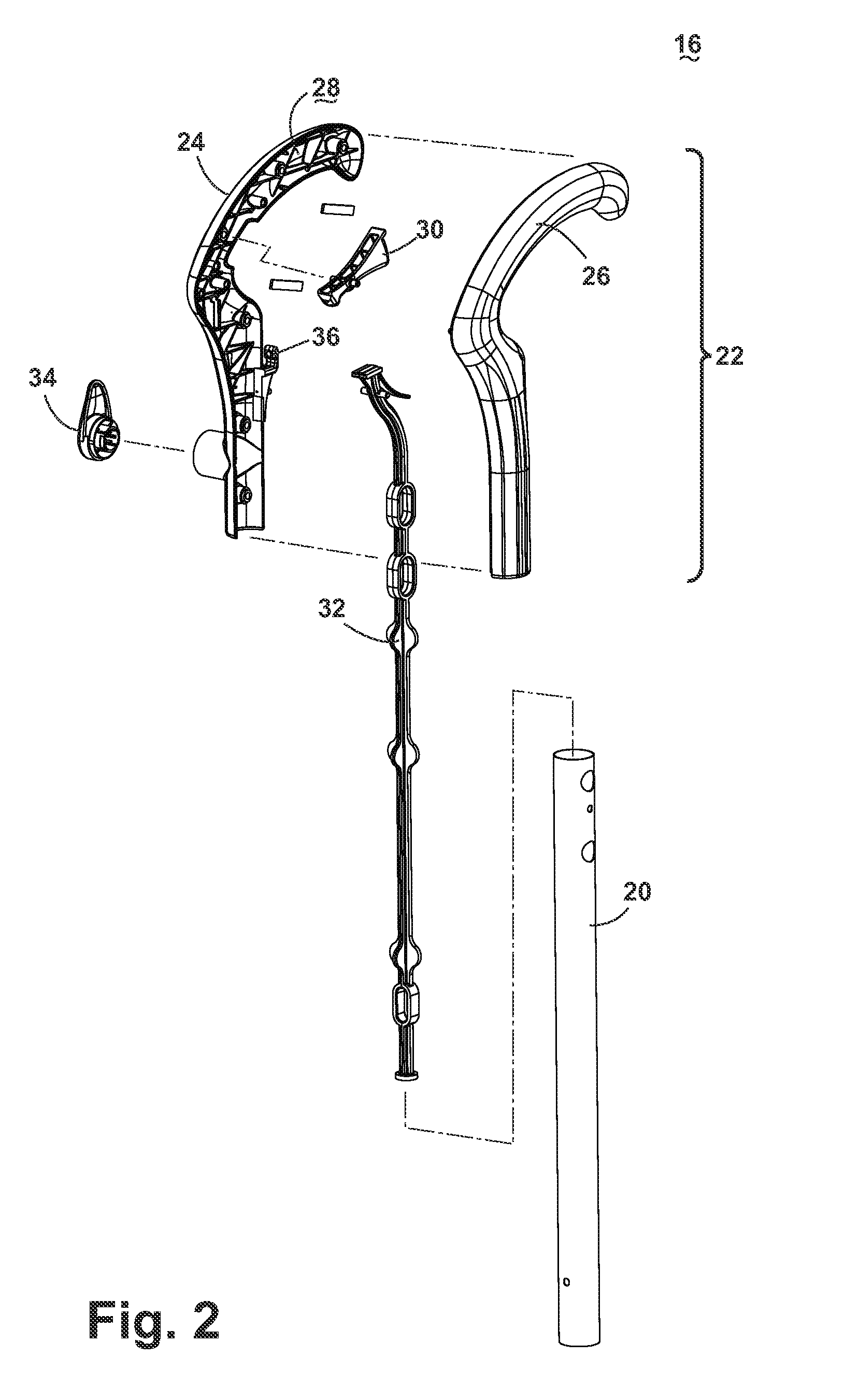
[0051]The handle assembly 12 comprises an upper handle assembly 16 and a lower handle assembly 18. The upper handle assembly 16 comprises a hollow handle tube 20 having a grip assembly 22 fixedly attached to a first end of the handle tube 20 and the lower ...


PUM


Abstract

An upright bare floor cleaner with a handle assembly pivotally mounted to a base assembly. The base assembly has a sweeper that includes a rotatably driven brush adapted to sweep dust and dirt particles into a removable dirt receptacle. The handle includes a water tank to store a quantity of water and a fluid distribution system that includes a heater and a spray nozzle. Steam is generated by the heater and is distributed to a removable mop cloth that applies the steam to the surface to be cleaned.

Description

CROSS-REFERENCE TO RELATED APPLICATION[0001]This application claims the benefit of U.S. Provisional Patent Application No. 61 / 177,391, filed May 12, 2009, which is incorporated herein by reference in its entirety.BACKGROUND OF THE INVENTION[0002]1. Field of the Invention[0003]This invention relates to an upright bare floor cleaner. In one aspect, the invention relates to a sweeper that performs dry pickup. In another aspect, the invention relates to a bare floor cleaner that selectively or simultaneously performs dry sweeping and steam mopping. In another aspect, the invention relates to an upright steam cleaner having a mop cloth to absorb moisture and to capture small dust and dirt particles not removed by the sweeper. In yet another aspect, the invention relates to an upright steam cleaner incorporating an easily mounted and removable mop cloth to absorb moisture and to capture small dust and dirt particles not removed by the sweeper.[0004]2. Description of the Related Art[0005]T...

Claims


Application Information

Patent Timeline
Patent Type & Authority Patents(United States)
IPC IPC(8): A47L7/00
CPCA47L11/4027A47L11/4041A47L11/26A47L13/22A47L13/225A47L11/4086A47L11/4013A47L11/4075A47L11/4083A47L11/4088
Inventor KASPER, GARY A.WHITE, JOSEPH M.JANSEN, JOHN L.GRIFFITH, AARON P.
Owner BISSELL INC
Why Eureka
Try Eureka