Wireless communication system, communication control method and communication node

a communication control and wireless communication technology, applied in power management, high-level techniques, instruments, etc., can solve problems such as difficult to reduce power consumption, data collisions, and limited slots to be used at gts within the super-frame, so as to extend the wireless communication system to a wider area, reduce power consumption, and reduce power consumption

a communication control and wireless communication technology, applied in power management, high-level techniques, instruments, etc., can solve problems such as difficult to reduce power consumption, data collisions, and limited slots to be used at gts within the super-frame, so as to extend the wireless communication system to a wider area, reduce power consumption, and reduce power consumption

US8503343B2Inactive Publication Date: 2013-08-06PANASONIC CORP

Image

  • Wireless communication system, communication control method and communication node
  • Wireless communication system, communication control method and communication node
  • Wireless communication system, communication control method and communication node

Examples


first embodiment

The First Embodiment

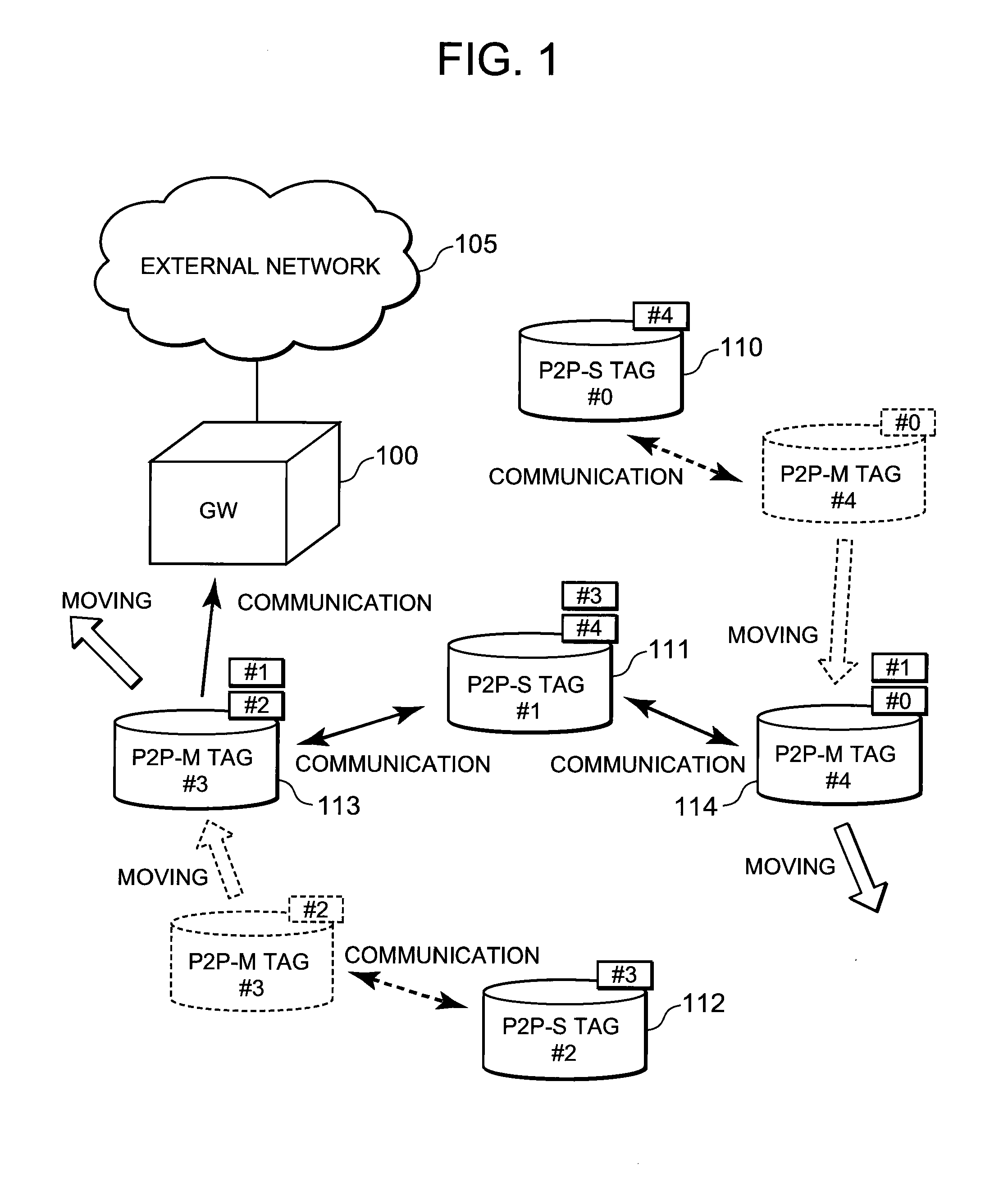
[0125]First, referring to FIG. 1, description will be given on a communication system, which comprises wireless nodes of different types in the first embodiment of the invention. FIG. 1 is a schematical drawing to show an example of a communication system, which comprises wireless nodes of different types in the first embodiment of the invention.

[0126]The communication system shown in FIG. 1 comprises a gateway (GW) 100 and a plurality of wireless nodes (wireless tags) 110 to 114. GW 100 is connected to an external network (e.g. Internet) 105 via wired / wireless means, and it is a communication node, which can communicate with the external network 105. It is desirable that GW 100 is fixed at a position where the power required for operation can be supplied via a given wiring.

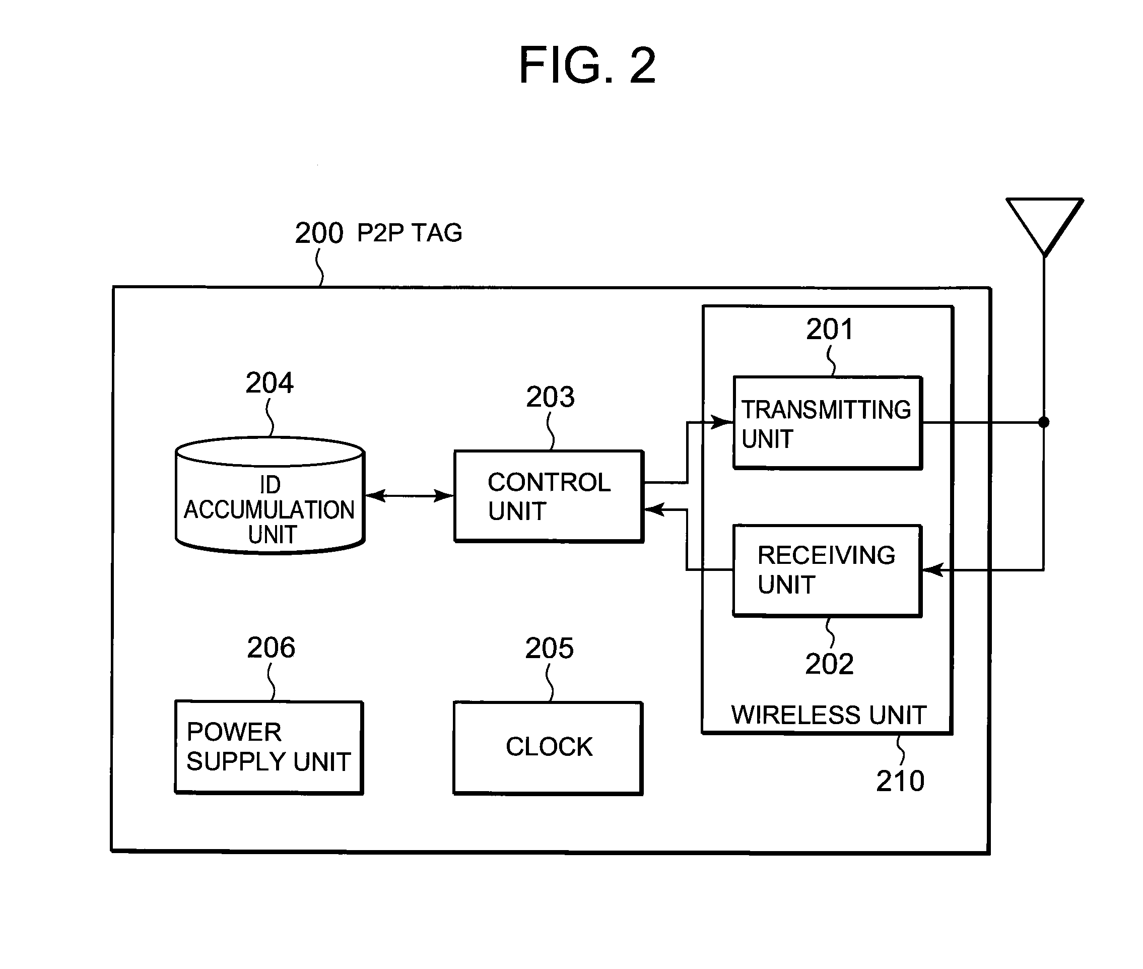
[0127]On the other hand, each of the wireless tags 110 to 114 is a small-type wireless tag (an active electronic tag) driven by battery, and it is a communication node, which can transmit and ...

second embodiment

The Second Embodiment

[0190]Next, description will be given on the second embodiment of the invention. FIG. 9 is a schematical drawing to illustrate a wireless communication network including a plurality of nodes 1 to 4 in the second embodiment of the invention. In FIG. 9, each of the plurality of nodes is a wireless communication node, which can directly communicate with other nodes present in the neighborhood (within wireless propagation range) of each of the nodes 1 to 4. Each of the nodes 1 to 4 can change the node, with which it can communicate when it moves. The nodes 1 to 4 may be mobile or may be fixedly set.

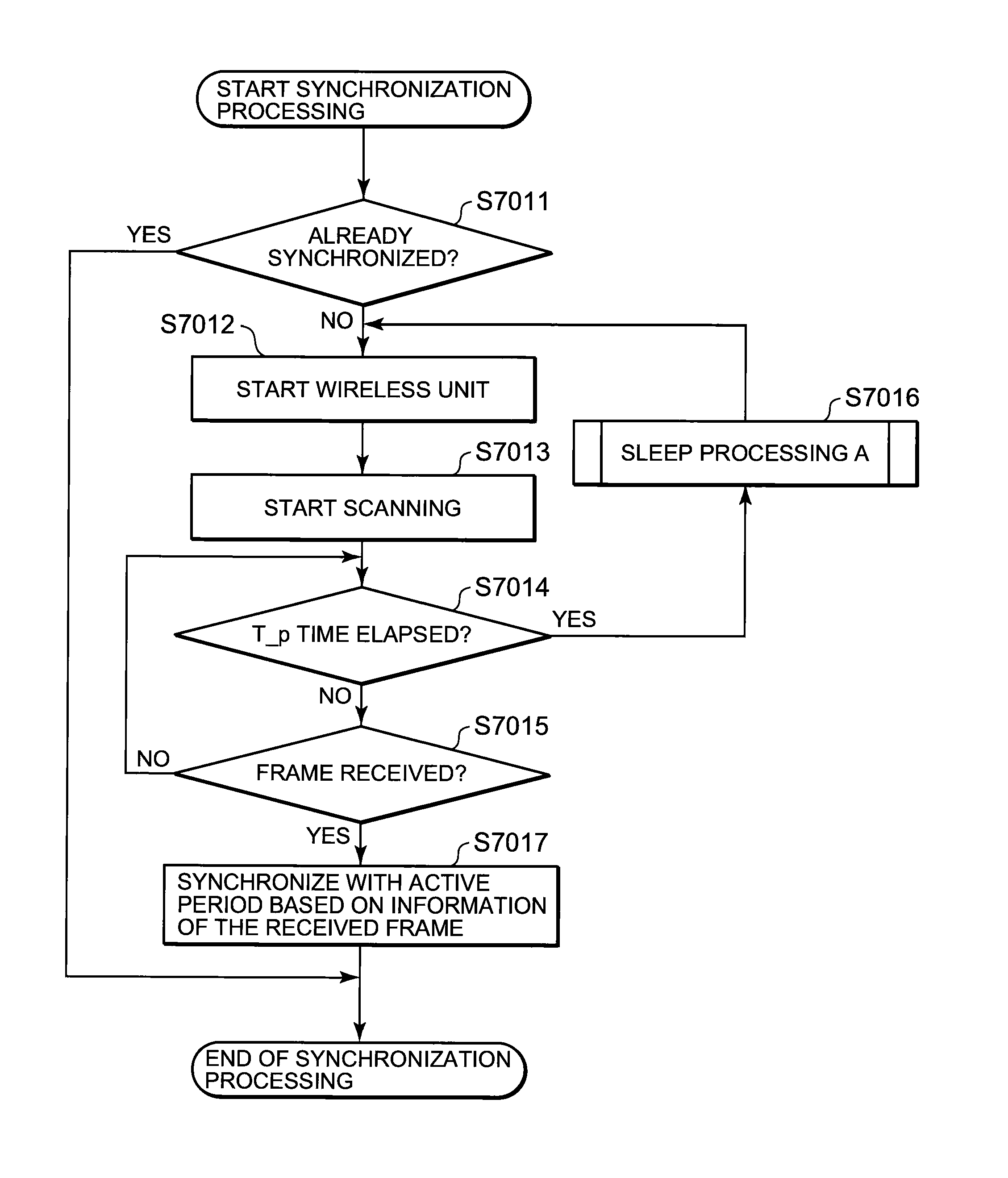
[0191]The nodes 1 to 4 are the nodes to perform wireless communication as described above. Each of these nodes is a node, which automatically starts and stops a receiver (hereinafter, may be referred as “Rx”) of the wireless unit. In the schedule of the starting and the stopping, by performing the synchronization between the nodes, each node can have the same schedule.

[01...


PUM


Abstract

A technique is disclosed, by which it is possible to achieve the reduction of power consumption of each wireless node and to perform efficient access control in wireless communication system. According to this technique, a given period with a beacon transmitted from a gateway (GW) 100 at the foremost position is divided to an active period where each wireless node (P2P tag) transmits and receives a frame and a sleep period where transmitting and receiving of the frames are stopped. Further, the active period is divided to a plurality of timeslots each with a fixed length, and the period is partitioned to sub-periods where each type of a GW, a fixed node (P2P-S tag), and a mobile node (P2P-M tag) can transmit frames respectively. Each of the P2P tags selects a timeslot at random from the period for each type, and after waiting for a waiting period at random at the selected timeslot, it transmits a frame including information to identify the selected timeslot or the waiting period in addition to its own ID.

Description

TECHNICAL FIELD[0001]The present invention relates to a wireless communication system, a communication control method and a communication node. In particular, the invention relates to a wireless communication system, a communication control method and a communication node for achieving media access control (MAC) with low power consumption in case a mobile communication node exchanges data bi-directionally.BACKGROUND ART[0002]In a wireless hardware of a wireless system, the reduction of power consumption is an important factor. In particular, in a wireless communication system, as examples of application, for which a power-saving mechanism is needed, there are an active electronic tag system, a sensor network system, etc. For sensor nodes in the active electronic tag or in the sensor network, portability and easy and flexible installation are important features. Normally, it is a battery type node incorporated with a small-size battery.[0003]The applications such as the active electr...

Claims


Application Information

Patent Timeline
06 Aug 2013
Publication
US8503343B2
IPC
G08C17/00
CPC
H04W52/0216; H04W48/08; H04W72/02; H04W74/04; Y02B60/50; Y02D30/70
Inventors
KAWAKAMI, TETSUYA; YOKOBORI, MICHIRU