Bone fixation system and method

a bone fixation system and bone technology, applied in the field of bone fixation system and bone fixation method, can solve the problems of one locking screw or non-locking screw, limited capacity of locking screw to compress bone fragments, and half of the screw hole may not be suitable for use, so as to improve the pull out strength of the plate, minimize soft tissue dissection, and excellent anti-torsional characteristics

Active Publication Date: 2014-05-20
STEFFEN DENNIS L
View PDF11 Cites 64 Cited by
  • Summary
  • Abstract
  • Description
  • Claims
  • Application Information

AI Technical Summary

Benefits of technology

[0015]Yet another object is to provide a bone Fixation system which optimizes the alignment and stabilization of the bone segments in the bone fracture being bridged by the plate.
[0017]An additional object of the invention is to provide a bone plate which minimizes the number of different screws required to secure the system's bone plate to a bone.
[0026]The full mechanical advantage of the combination bole configuration in accordance with the invention is realized when two screws are mated to the same bi-directional or bi-angular hole. The head of the first screw mated to the plate is suitably positioned to allow the placement in the same combination hole of a second similar or different screw. Having two fixed-angle screws oriented in divergent directions into the substance of the bone enhances the pull out strength of the plate from the bone far beyond that of a single screw oriented perpendicular to the plate. In the preferred embodiment of the invention, the two screws in each combination hole of the bone plate form an inverted A frame configuration which also exhibits excellent anti-torsional characteristics.
[0027]It should also be noted that during the surgical act of applying the plate to the fractured bone, critical vessels or nerves, muscle or other soft tissue may be in the way of the path of the intended drill hole in the bone, in accordance with the invention, a surgeon is able to avoid undue retraction on the soft tissue or even to minimize soft tissue dissection by choosing the more suitable direction afforded by the bi-directional hole design in the bone plate. Therefore, an additional benefit of the bi-directional design is its versatility, minimizing the requirement for soft tissue dissection and retraction.

Problems solved by technology

However, locking screws have a limited capability to Compress bone fragments.
However, only a one locking or a non-locking screw can be applied in each of these “combination” holes along the bone plate.
However, for such a configuration, half of the screw holes may not be suitable for use.
While this last system has certain advantages, it also has a drawback in that the by-pass screw must he screwed into one domain of a combination hole in the bone plate so that the flat side of its head faces the other domain of that hole to provide the needed clearance for the second screw being installed in that other domain.
In many instances, in order to do this, the by-pass screw may have to be undertightened or overtightened into the underlying bone in order to bring the head fiat in register with the other domain of the same hole, If that screw is undertightened, the bone plate may not be drawn sufficiently to the bone to stabilize the bone fracture.
On the other hand, if that screw is overtightened, the screw threads may he stripped from the bone.
Another disadvantage of using bone screws with by-pass heads is that it increases the size of the screw inventory required to he maintained in hospitals, clinics and the like.
The use of such screws with by-pass heads also complicates the surgical implantation of the plates in that the surgeon has to be be sure that he is installing the correct screw in each screw hole of the bone plate.

Method used


Image

  • Bone fixation system and method
  • Bone fixation system and method
  • Bone fixation system and method

Examples


Embodiment Construction

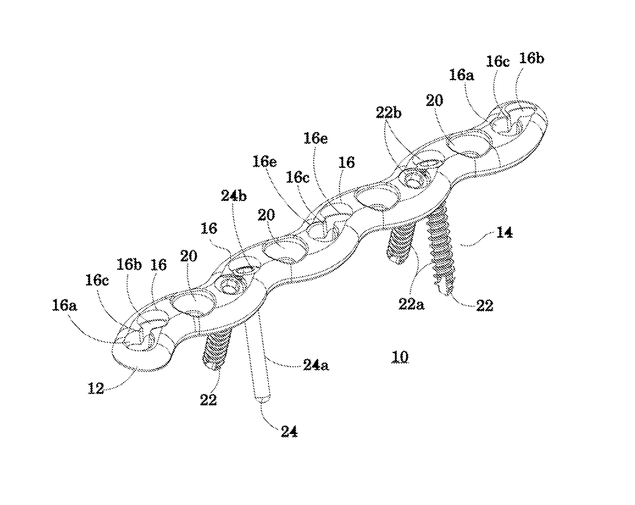
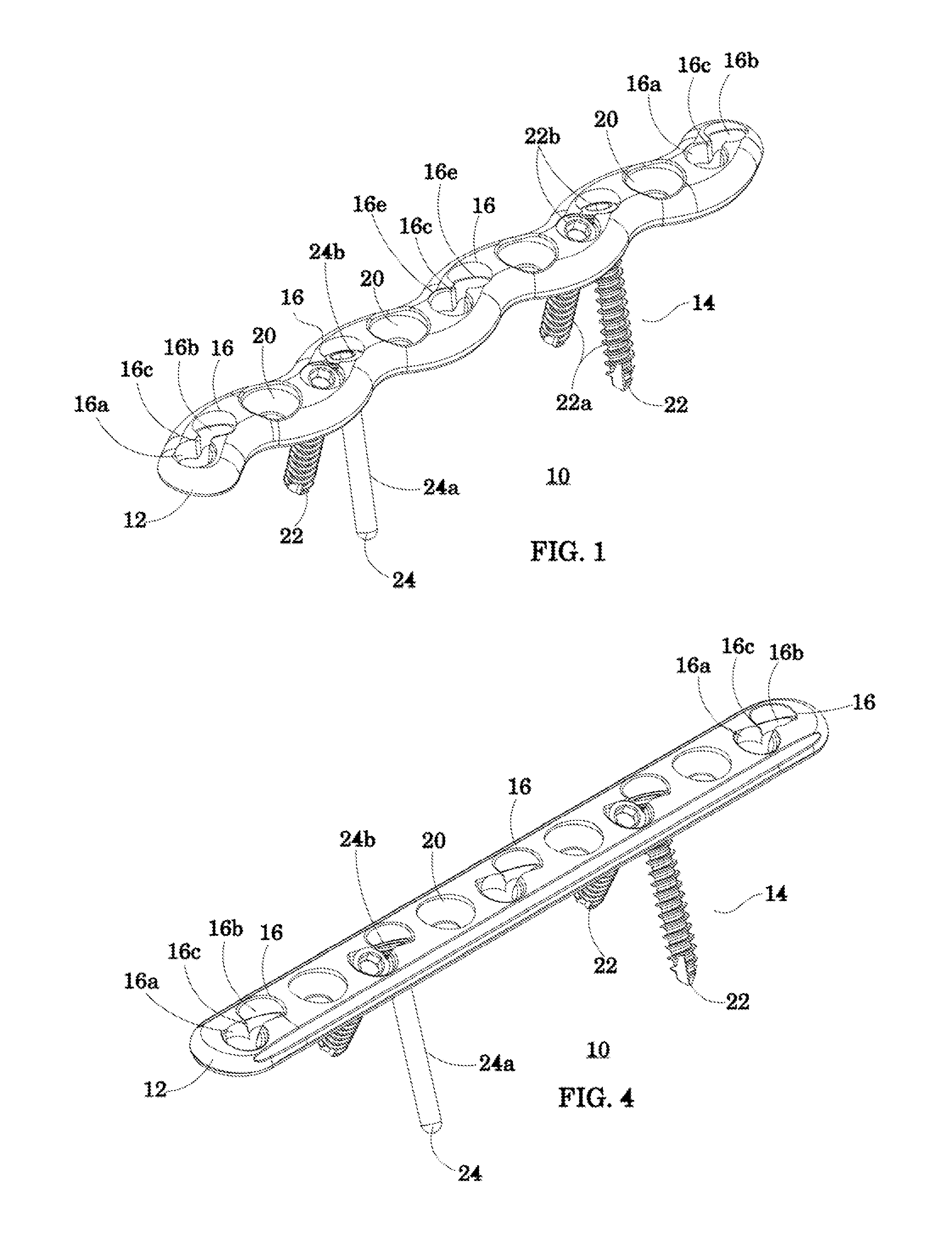
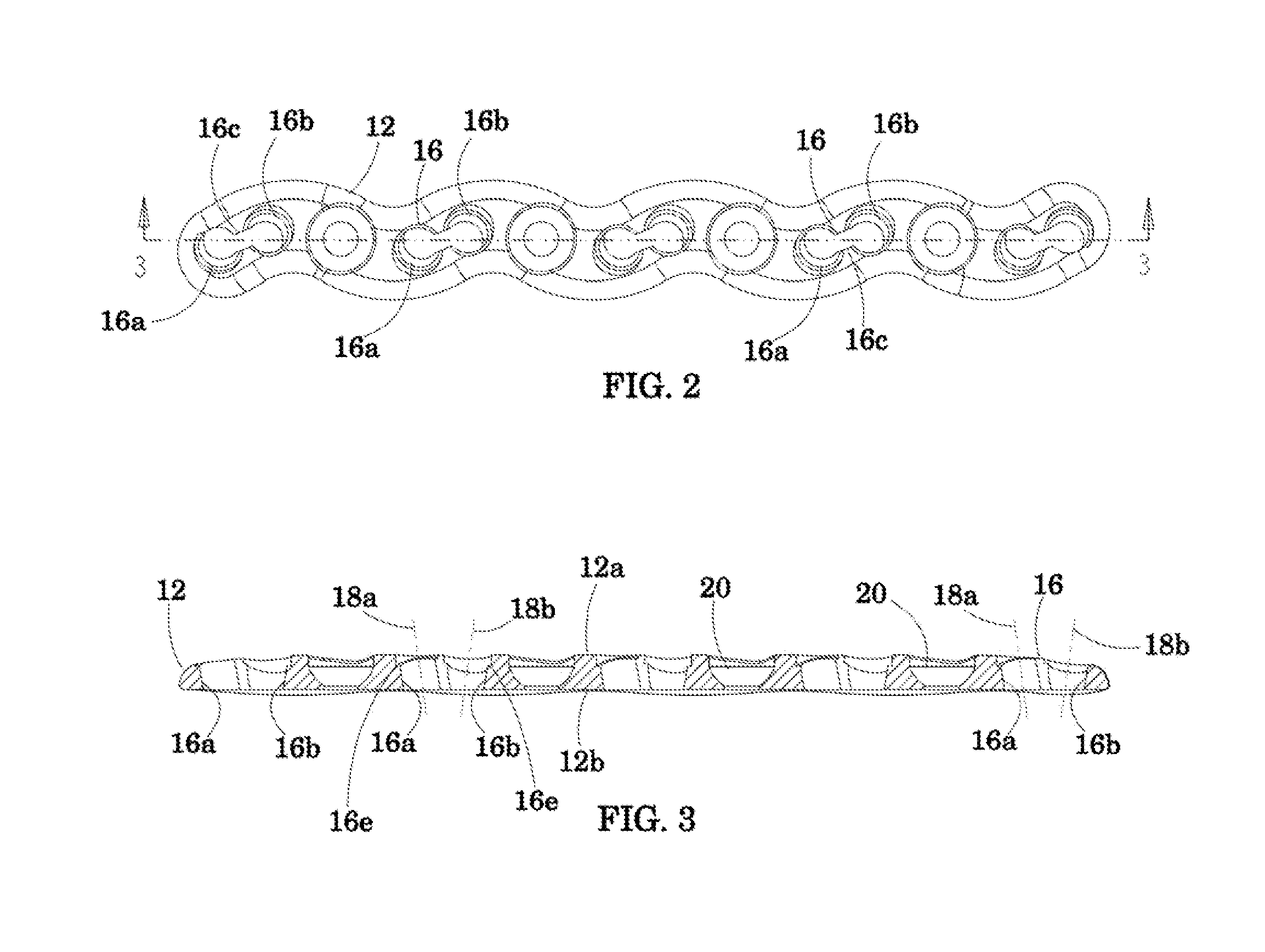
[0041]Referring to FIGS. 1-3 of the drawings, my bone fixation system shown generally at 10 comprises an elongated bone plate 12 made of a suitable rigid biocompatible metal such as titanium or stainless steel and a screw set indicated at 14, of a similar metal, for anchoring the bone plate to the bone to be fixated. The particular dimensions and shape of the bone plate 12 depend upon the size and shape of the bone and the length and dispersion of the bone fracture to he bridged by the plate.

[0042]Plate 12 has a first or upper surface 12a and a lower, bone-contacting surface 12b opposite surface 12a. Extending between those surfaces is a lengthwise series of spaced-apart combination holes or apertures 16 disposed along the longitudinal axis of plate 12. Each hole 16 has a predefined shape and size. More particularly, each hole 16 is composed of as pair of substantially circular domains 16a and 16b with a counter-bore 16e and which are offset laterally from one another about the plat...


PUM


Abstract

A bone fixation system includes a bone plate having bi-directional combination holes extending therethrough, each hole being composed of a pair of domains and an interconnect which prevents the holes from overlapping. Each of the holes is configured and dimensioned to receive a set of full head bone screws adapted to be anchored into a bone or fragments thereof. The system also includes a pair of bone screws received in at least one of the combination holes, each bone screw having a shaft and a full head and being oriented in non-parallel directions. Various bone plate and screw embodiments are disclosed as is a method for fixating a bone fracture using the fixation system.

Description

CROSS-REFERENCE TO RELATED APPLICATIONS[0001]This application is a continuation-in-part of U.S. Ser. No. 12 / 398,882, filed Mar. 5, 2009, which claims the benefit of Provisional Application Ser. No. 61 / 035,138, filed Mar. 10, 2008, the entire contents of which are hereby incorporated by reference herein.BACKGROUND OF THE INVENTION[0002]1. Field of the Invention[0003]The present invention relates to a bone fixation system and method for fracture fixation of bone.[0004]Conventional bone fixation systems include a bone fracture fixation plate for placement on a bone so as to bridge a fracture therein and a set of screws inserted through the plate into the bone. The system works by drawing the fracture fragments to the plate, and if the plate is designed with “compression” holes, the fracture fragments can be made to compress against each other to promote primary bone healing. However, the angular relationship between the plate and screws is not fixed and can change postoperatively. As s...

Claims


Application Information

Patent Timeline
Patent Type & Authority Patents(United States)
IPC IPC(8): A61B17/80
CPCA61B17/8057A61B17/8014A61B17/8605
Inventor STEFFEN, DENNIS, L.
Owner STEFFEN DENNIS L
Why Eureka
Try Eureka