
Height adjustment device for a vehicle seat
a technology for vehicle seats and height adjustment, which is applied in the direction of vehicle components, belt anchoring devices, vehicle arrangements, etc., can solve the problems of increasing the force that may act on the connection points, and achieve the effect of reducing the alteration of the height adjustable underfram
- Summary
- Abstract
- Description
- Claims
- Application Information
AI Technical Summary
Benefits of technology
Problems solved by technology
Method used
Image

Examples
Embodiment Construction
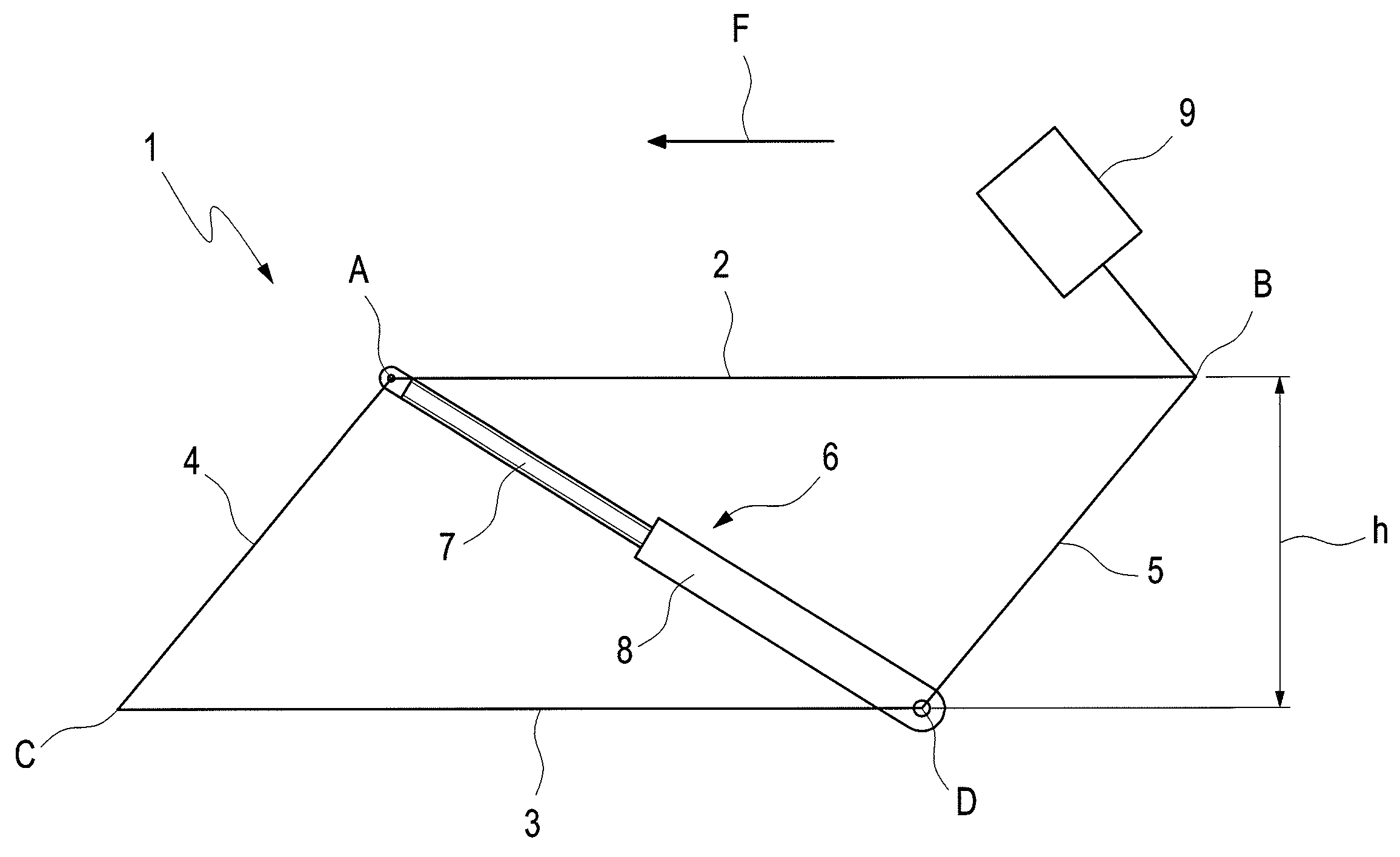
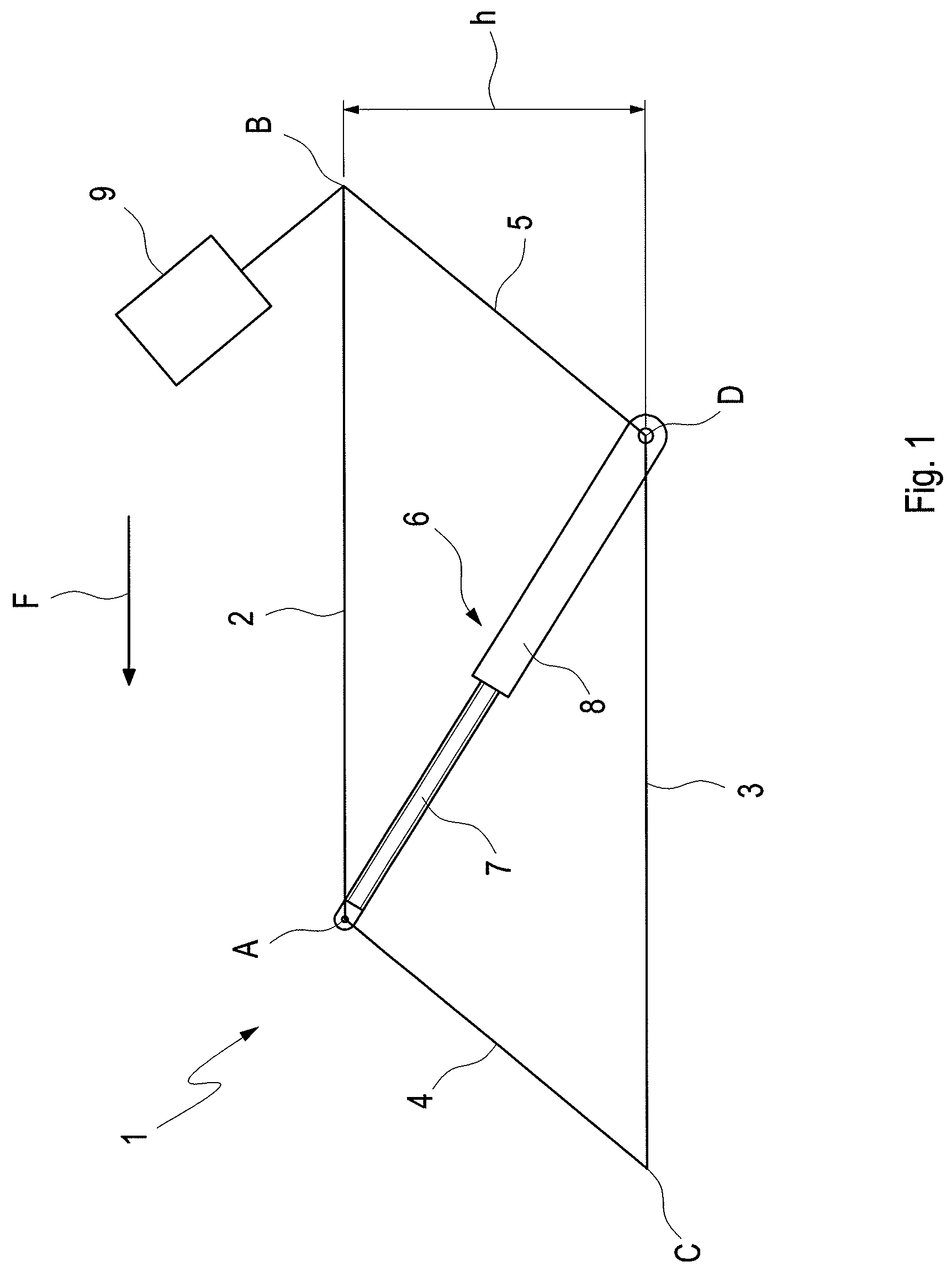
[0022]FIG. 1 shows the adjustment parallelogram 1 diagrammatically in order to illustrate the principle of construction more clearly. The seat frame part 2, the upper rail 3, a first lateral link 4 and a second lateral link 5 are shown as basic components of the adjustment parallelogram 1. The seat frame part 2 and upper rail 3 are connected together in rotary articulated manner by the two lateral links 4, 5 at the corners A, B, C, D of the parallelogram.
[0023]The spindle drive 6 connects two obliquely opposing corners A, D, and consists of a threaded rod 7 and a threaded sleeve 8. The threaded rod 7 is attached pivotably to the corner A, and is axially rotatable about its longitudinal axis. The threaded sleeve 8 is attached pivotably to the corner D. The threaded rod 7 can be turned in a known manner, for example, by an electric motor (not shown in the drawing), or by a mechanical rotary wheel (likewise not shown in the drawing). The threaded rod 7 engages with its thread in a thre...
PUM
 Abstract
Description
Claims
Application Information