Shutter unit for vehicle

Active Publication Date: 2014-08-05
HONDA MOTOR CO LTD
View PDF18 Cites 23 Cited by
  • Summary
  • Abstract
  • Description
  • Claims
  • Application Information

AI Technical Summary

Benefits of technology

[0006]It is an object of the present invention to provide a shutter unit for a vehicle, which is capable of properly determining failure of a shutter without using a sensor which directly detects a position of the shutter.

Problems solved by technology

On the other hand, when the shutter is faulty, since the shutter is hardly moved by urging of the urging means, and is in a stuck state, motive power is hardly transmitted from the shutter to the rotating machine during execution of the return control, and as a result, the rotating machine induced voltage is hardly generated.

Method used


Image

  • Shutter unit for vehicle
  • Shutter unit for vehicle
  • Shutter unit for vehicle

Examples


Embodiment Construction

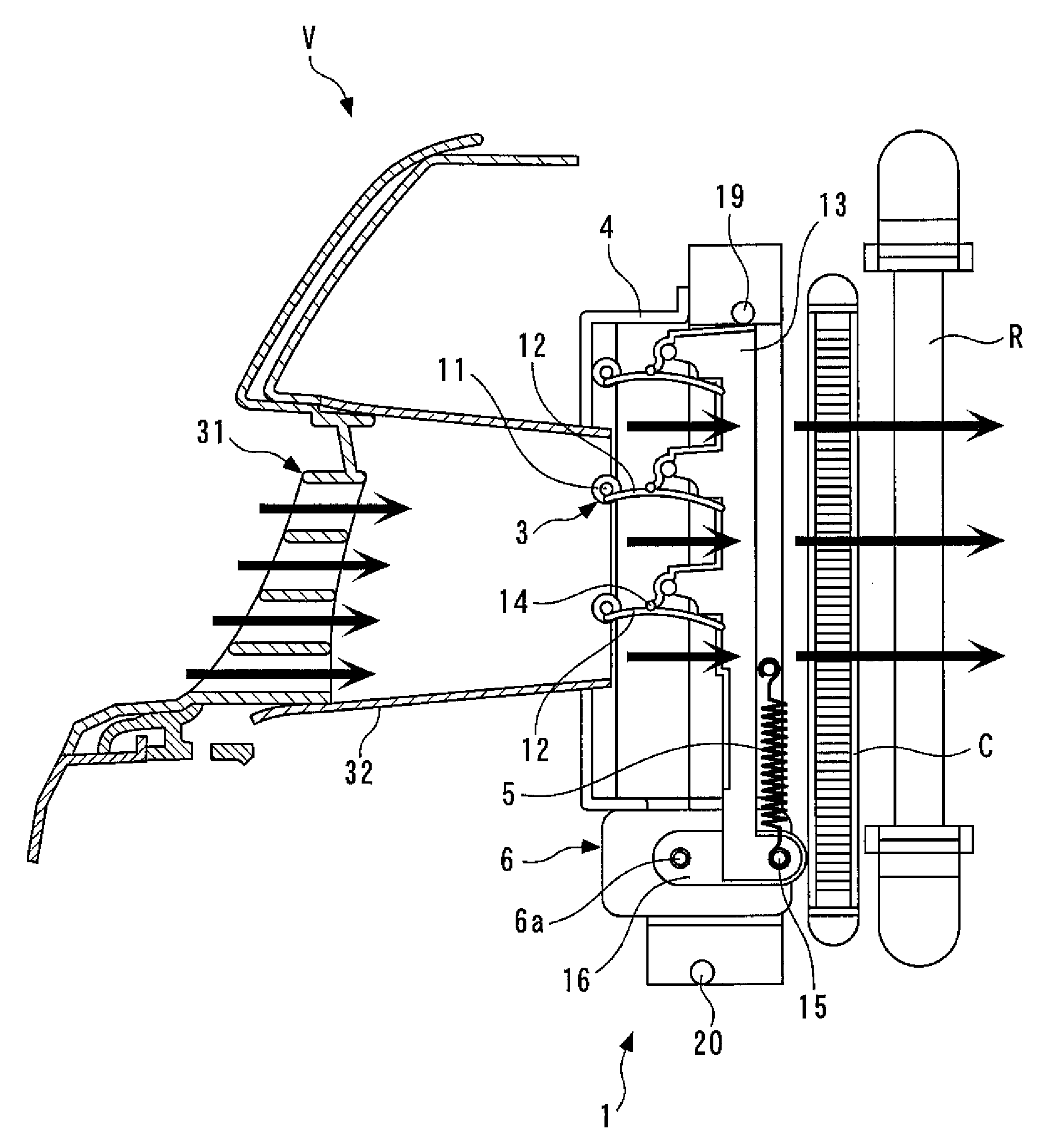
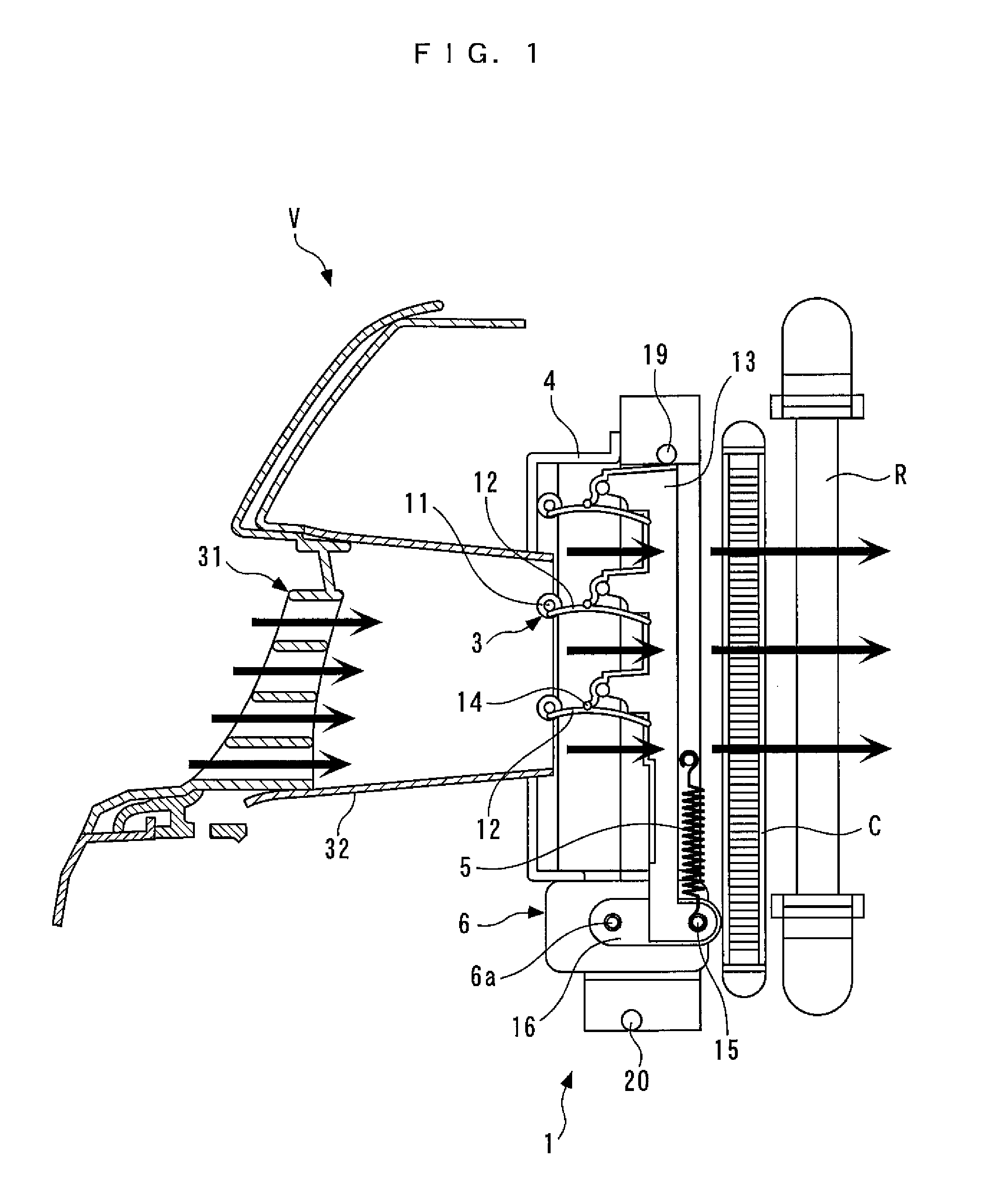
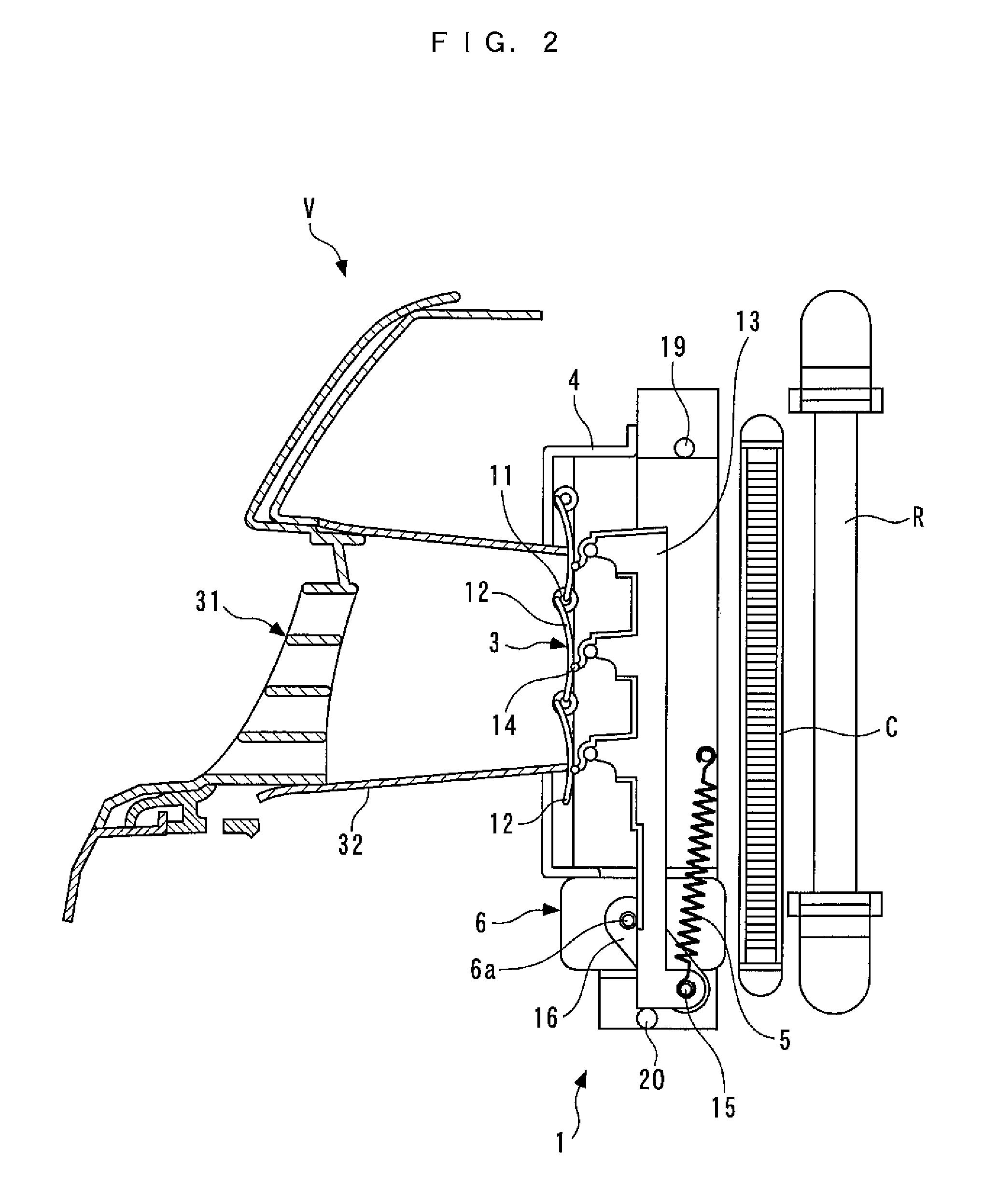
[0034]The invention will now be described in detail with reference to drawings showing a preferred embodiment thereof. A shutter unit 1 shown in FIG. 1 is provided in a front part of a vehicle V together with a grill 31 and a duct 32, and a condenser C and a radiator R are provided at respective locations rearward of the shutter unit 1. During traveling of the vehicle V, outside air is guided to the condenser C and the radiator R by the grill 31 and the duct 32. The condenser C forms a refrigeration cycle for an air conditioner (not shown) of the vehicle V, together with a compressor, an evaporator (neither of which is shown), etc. Further, the radiator R is for cooling an internal combustion engine (not shown) as a power source of the vehicle V.

[0035]As shown in FIG. 1, the shutter unit 1 comprises a shutter 3 for adjusting a flow rate of outside air introduced into the condenser C etc., a shutter base 4 which supports the shutter 3, a return spring 5 for returning the shutter 3 to...


PUM


Abstract

A shutter unit for a vehicle, capable of properly determining failure of a shutter without using a sensor which directly detects a position of the shutter. The shutter unit includes a return spring for returning the shutter to a predetermined initial position by urging the shutter, and a rotating machine configured to be capable of converting input motive power to electrical power and input electrical power to motive power by electromagnetic induction action. The rotating machine drives the shutter by the motive power obtained by conversion. The shutter unit executes return control that stops supply of electric power to the rotating machine to return the shutter to the initial position by urging of the shutter by the return spring, and determines failure of the shutter based on a rotating machine induced voltage of the rotating machine, detected during execution of the return control.

Description

BACKGROUND OF THE INVENTION[0001]1. Field of the Invention[0002]The present invention relates to a shutter unit for a vehicle, provided on a front part of a vehicle, for adjusting an amount of outside air introduced into the front part.[0003]2. Description of the Related Art[0004]Conventionally, a shutter unit for a vehicle of this kind has been proposed in Japanese Laid-Open Utility Model Publication (Kokai) No. S59-114412. This shutter unit is for adjusting a flow rate of outside air flowing through a radiator which cools an internal combustion engine of a vehicle, and is disposed in a front grill of the vehicle. Further, the shutter unit comprises a shutter formed by a plurality of pivotally movable blades and driving means. The driving means opens and closes the shutter, to thereby adjust the flow rate of outside air flowing through the radiator. Further, the shutter is provided with a spring for urging the shutter toward an open position. In this conventional shutter unit, even...

Claims


Application Information

Patent Timeline
Patent Type & Authority Patents(United States)
IPC IPC(8): B60K11/00B60K11/08G06F7/00G06F17/00
CPCB60K11/085Y02T10/88
Inventor NEMOTO, HIROTOMI
Owner HONDA MOTOR CO LTD
Why Eureka
Try Eureka