Exhaust apparatus of air-cooled fuel cell vehicle

a fuel cell vehicle and exhaust apparatus technology, applied in the direction of fuel cells, special dispensing means, branching pipes, etc., can solve the problems of increased size, weight and cost of the system, and achieve the effect of reducing ventilation loss and improving the exhaust performance of hydrogen gas having a specific gravity smaller than that of air

Active Publication Date: 2014-09-02
SUZUKI MOTOR CORP
View PDF14 Cites 8 Cited by
  • Summary
  • Abstract
  • Description
  • Claims
  • Application Information

AI Technical Summary

Benefits of technology

[0013]In the exhaust apparatus of the air-cooled fuel cell vehicle according to the present invention, the exhaust duct of the air-cooled fuel cell stack is composed of the lower side exhaust duct and the upper side exhaust duct which are branched vertically, and thereby the passage sectional area of the exhaust duct is increased, so as to reduce the ventilation loss. Further, in the exhaust apparatus of the air-cooled fuel cell vehicle according to the present invention, the lower side exhaust duct is extended toward the lower side of the vehicle from the exhaust outlet portion of the air-cooled fuel cell stack, and the downstream end portion of the lower side exhaust duct is opened at a lower portion of the front compartment, while the upper side exhaust duct is extended toward the upper side of the vehicle from an upper portion of an outer wall of the lower side exhaust duct, the outer wall extending toward the lower side of the vehicle, and the downstream end portion of the upper side exhaust duct is opened between the rear end portion of the front hood and the front end portion of the front window. For this reason, in the exhaust apparatus of the air-cooled fuel cell vehicle according to the present invention, the upper side exhaust duct can be opened upward with a shortest distance. Thereby, the exhaust performance of hydrogen gas having specific gravity smaller than that of air can be improved, and water and foreign matter, which flow into the upper side exhaust duct from the downstream end portion of the upper side exhaust duct, are made to flow to the side of the downstream side exhaust duct, so that the water and foreign matter can prevented from intruding into the air-cooled fuel cell stack.

Problems solved by technology

For this reason, in the water-cooled fuel cell vehicle system 101, the system is complicated, and also the size, weight and cost of the system are increased.

Method used


Image

  • Exhaust apparatus of air-cooled fuel cell vehicle
  • Exhaust apparatus of air-cooled fuel cell vehicle
  • Exhaust apparatus of air-cooled fuel cell vehicle

Examples


example

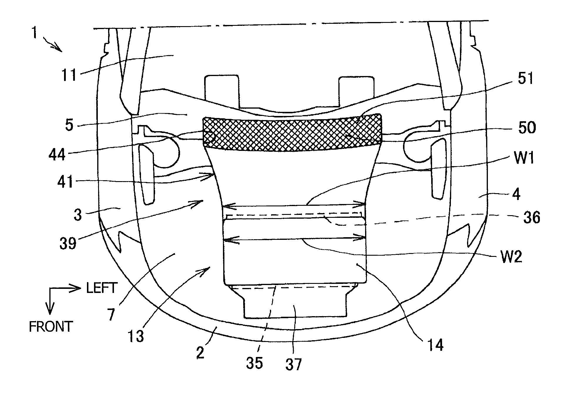
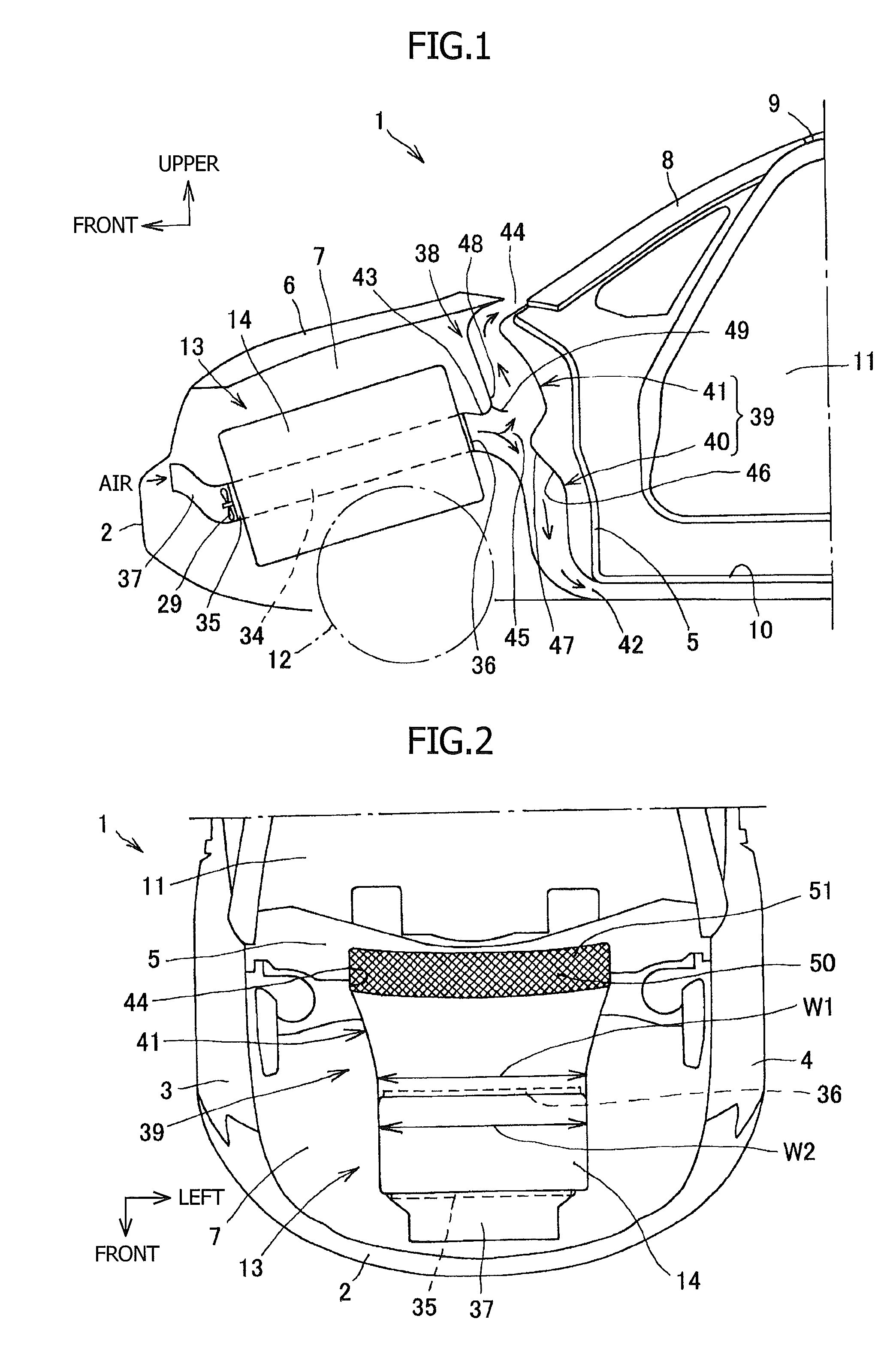
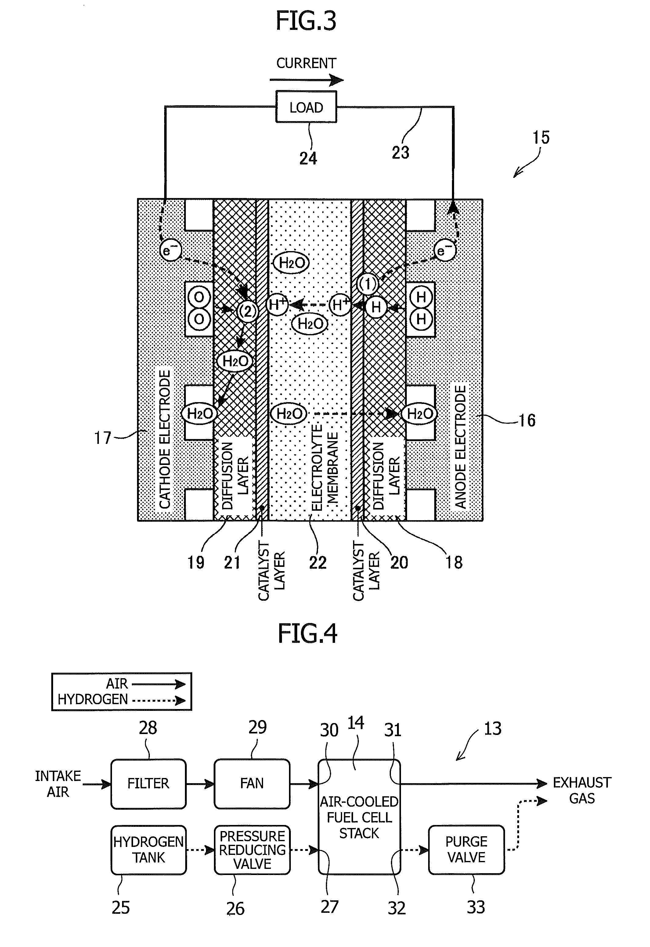
[0020]FIG. 1 to FIG. 4 show an example according to the present invention. In FIG. 1 and FIG. 2, reference numeral 1 denotes an air-cooled fuel cell vehicle, reference numeral 2 denotes a front bumper, reference numeral 3 denotes a right fender apron, reference numeral 4 denotes a left fender apron, reference numeral 5 denotes a dash panel, reference numeral 6 denotes a front hood, reference numeral 7 denotes a front compartment, reference numeral 8 denotes a front window, reference numeral 9 denotes a roof panel, reference numeral 10 denotes a floor panel, reference numeral 11 denotes a vehicle compartment, and reference numeral 12 denotes a front wheel. In the air-cooled fuel cell vehicle 1, the front compartment 7 is formed by being surrounded by the front bumper 2, the right and left fender aprons 3 and 4, and the dash panel 5 and by being covered by the front hood 6. The vehicle compartment 11 surrounded by the front window 8, the roof panel 9, the floor panel 10, and right and...


PUM

PropertyMeasurementUnit
dimensionaaaaaaaaaa
pressureaaaaaaaaaa
flow rateaaaaaaaaaa

Abstract

An exhaust apparatus includes a lower side exhaust duct and an upper side exhaust duct which are branched vertically, and in that the lower side exhaust duct is extended toward the lower side of the vehicle from an exhaust outlet portion of the air-cooled fuel cell stack, and the downstream end portion of the lower side exhaust duct is opened at a lower portion of the front compartment, while the upper side exhaust duct is extended toward the upper side of the vehicle from an upper portion of an outer wall of the lower side exhaust duct, the outer wall extending toward the lower side of the vehicle, and the downstream end portion of the upper side exhaust duct is opened between the rear end portion of the front hood and the front end portion of the front window.

Description

RELATED APPLICATIONS[0001]This application is a 35 U.S.C. §371 national stage application of PCT Application No. PCT / JP2011 / 061833, filed on May 24, 2011, which claims priority from Japanese Application No. 2010-122579 filed May 28, 2010, the contents of which are incorporated herein by reference in their entireties. The above-referenced PCT International Application was published as International Publication No. WO 2011 / 148927 A1 on Dec. 1, 2011.TECHNICAL FIELD[0002]The present invention relates to an exhaust apparatus of an air-cooled fuel cell vehicle, and in particular, relates to an exhaust apparatus of an air-cooled fuel cell vehicle which improves the exhaust performance of an air-cooled fuel cell stack arranged in a front compartment of the vehicle and which prevents intrusion of water and foreign matter into the air-cooled fuel cell stack.BACKGROUND ART[0003]In vehicles in which a fuel cell stack formed by stacking a plurality of fuel-cell cells is used as a drive energy so...

Claims


Application Information

Patent Timeline
Patent Type & Authority Patents(United States)
IPC IPC(8): B67D7/80B05B1/24B60K1/00B60K1/04B60K11/06B60L1/00B60L11/18F16L41/02H01M8/04H05B3/00
CPCF16L41/02B60L1/003B60L11/1896H01M8/04156B60L11/1894H01M8/04014H05B3/00B60L11/1898B60L11/1892B60K1/04B60K11/06Y02T90/34B60K2001/005H01M2250/20Y02E60/50B60K2001/003Y02T90/32B60K2001/0411Y10T137/85938B60L50/71B60L50/72B60L58/33B60L58/34Y02T90/40B60K8/00B60K13/04H01M8/00
Inventor OHTSUKA, RYUJIMATSUMOTO, YOSHIMASAOHTA, TOHRUIKEYA, KENGO
Owner SUZUKI MOTOR CORP
Why Eureka
Try Eureka