
Multi-link crank linkage and method for operating the same

A crank linkage mechanism and multi-link technology, applied in the direction of machines/engines, mechanical equipment, combustion engines, etc., can solve problems affecting the smooth operation of internal combustion engines, reduce knocking tendency, reduce ventilation loss, and improve Effect of Combustion Gas Pressure

Active Publication Date: 2020-08-21
AUDI AG
View PDF9 Cites 0 Cited by
  • Summary
  • Abstract
  • Description
  • Claims
  • Application Information

AI Technical Summary

Problems solved by technology

This affects the smooth operation of the internal combustion engine

Method used


Image

  • Multi-link crank linkage and method for operating the same
  • Multi-link crank linkage and method for operating the same
  • Multi-link crank linkage and method for operating the same

Examples


Embodiment Construction

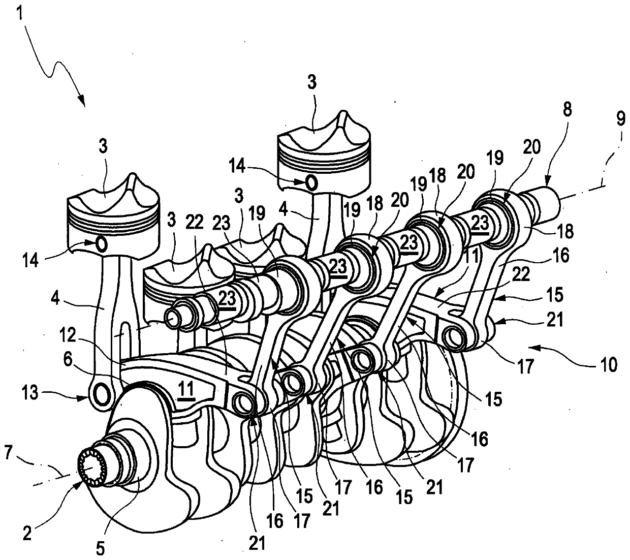
[0028] figure 1 A perspective view of a region of an internal combustion engine 1 is shown, which is present, for example, as a serial internal combustion engine, in particular a four-stroke four-cylinder serial internal combustion engine. Internal combustion engine 1 has a crankshaft 2 and a plurality of pistons 3 (here: four pistons 3 ), wherein each piston is movably mounted in one of the plurality of cylinders of internal combustion engine 1 . Each of the pistons 3 is connected to the crankshaft 2 via a piston connecting rod 4 . The crankshaft 2 is rotatably mounted in bearings, also not shown, of a cylinder crankcase (not shown here) of the internal combustion engine 1 and has, for example, a plurality of central journals 5 for bearing and a plurality of pin journals 6 (of which only one can be seen in each case in the figures), their longitudinal center axes are offset in different angular orientations parallel to the axis of rotation 7 of the crankshaft 2 .

[0029] T...


PUM


Abstract

The invention relates to a multi-link crank-and-rod mechanism (10) of an internal combustion engine (1), which has a plurality of connecting-rod journals (6) rotatably supported on a crankshaft (2). ) on the coupling (11) and a plurality of articulated links (15) supported on the connecting rod journal (19) of the eccentric shaft (8) in a rotatable manner, wherein each coupling (11) It is connected in a pivotable manner to a piston connecting rod (4) of a piston (3) of an internal combustion engine (1) and to one of the hinged connecting rods (15). It is stipulated here that, in order to reduce the second-order free inertial force, the multi-link crank linkage (10) is designed or adjusted in such a way that the range of the crankshaft rotation angle in the intake stage is greater than 180 degrees; the crankshaft rotation angle in the compression stage The range is less than 180 degrees; the crank angle range of the expansion stage is greater than 180 degrees; and the crank angle range of the exhaust stage is less than 180 degrees. The invention also relates to a method for operating a multi-link crankshaft (10) of an internal combustion engine (1).

Description

technical field [0001] The invention relates to a multi-link crank-and-rod mechanism of an internal combustion engine, the multi-link and crank-and-rod mechanism having a plurality of coupling parts rotatably supported on a crankshaft crankshaft journal and a plurality of rotatably The articulated connecting rods are supported on the connecting rod pins of the eccentric shaft, wherein each coupling part is pivotably connected to the piston connecting rod of the piston of the internal combustion engine and is connected to one of the articulated connecting rods. The invention also relates to a method for operating such a multi-link crank mechanism. Background technique [0002] A multi-link crank mechanism of the aforementioned type is, for example, a component of an internal combustion engine, but can also be used in other ways. The multi-link crank mechanism includes an eccentric shaft, the angle of rotation of which can preferably be adjusted by means of an adjusting devic...

Claims


Application Information

Patent Timeline
Patent Type & Authority Patents(China)
IPC IPC(8): F02B75/04
CPCF02B75/045F02B41/04F02B75/048
Inventor M·布伦德尔M·迈耶
Owner AUDI AG
Learn More