Cavitation roller capable of continuously making caves to plant cotton nutritive bowls by rotation

A nutrient bowl and cotton technology, applied in planting methods, excavation/covering of trenches, applications, etc., can solve the problems of inaccurate control of hole spacing, row spacing, large inertial force of hole-forming equipment, uneven hole depth, etc. Improve the efficiency of hole making, small inertial force and uniform hole depth

Inactive Publication Date: 2010-04-07
UNIV OF JINAN
View PDF0 Cites 10 Cited by
  • Summary
  • Abstract
  • Description
  • Claims
  • Application Information

AI Technical Summary

Problems solved by technology

Therefore, the cavitation equipment has problems such as large inertial force, inaccurate control of hole spacing and row spacing, uneven hole depth, and easy collapse of hole walls.

Method used


Image

  • Cavitation roller capable of continuously making caves to plant cotton nutritive bowls by rotation
  • Cavitation roller capable of continuously making caves to plant cotton nutritive bowls by rotation
  • Cavitation roller capable of continuously making caves to plant cotton nutritive bowls by rotation

Examples


Embodiment 1

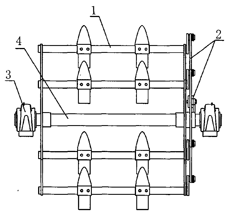
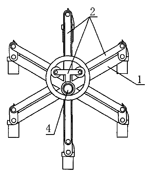
[0025] The cavitation roller includes a knife roller assembly 1, an eccentric adjustment device 2, a bearing seat 3 and a mandrel 4, the knife roller assembly 1 is installed on the mandrel 4, and the eccentric adjustment device 2 is installed on one side of the knife roller assembly 1, The two ends of the mandrel 4 are equipped with bearing blocks 3 connected with the frame.

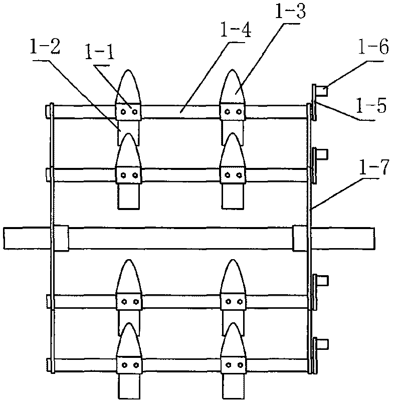
[0026] The cutter roller assembly 1 includes a cutter setter 1-1, a hole forming cutter 1-2, a soil throwing board 1-3, a connecting pipe 1-4, a connecting plate 1-5, a small short shaft 1-6 and a mounting frame 1- 7; The mounting frame 1-7 is a device similar to a "meter" shape in which four knife bars 1-9 are evenly arranged radially outwards from the same circle center. There is a round hole at the top of each knife bar 1-9, and all knife bars 1-9 The round holes on the top are on the same circumference; there are two mounting frames 1-7, and the two mounting frames 1-7 are installed on both sides of ...

Embodiment 2

[0029] The cavitation roller includes a knife roller assembly 1, an eccentric adjustment device 2, a bearing seat 3 and a mandrel 4, the knife roller assembly 1 is installed on the mandrel 4, and the eccentric adjustment device 2 is installed on one side of the knife roller assembly 1, The two ends of the mandrel 4 are equipped with bearing blocks 3 connected with the frame.

[0030] The cutter roller assembly 1 includes a cutter setter 1-1, a hole forming cutter 1-2, a soil throwing board 1-3, a connecting pipe 1-4, a connecting plate 1-5, a small short shaft 1-6 and a mounting frame 1- 7; The installation frame 1-7 is a device similar to the "meter" shape of eight knife bars 1-9 evenly arranged radially outwards from the same circle center. There is a round hole at the top of each knife bar 1-9, and all knife bars 1-9 The round holes on the top are on the same circumference; there are two mounting frames 1-7, and the two mounting frames 1-7 are installed on both sides of the...

Embodiment 3

[0033] The cavitation roller includes a cutter roller assembly 1, an eccentric adjustment device 2, a bearing seat 3 and a mandrel 4, the cutter roller assembly 1 is installed on the mandrel 4, and the eccentric adjustment device 2 is installed on one side of the cutter roller assembly 1, The two ends of the mandrel 4 are equipped with bearing blocks 3 connected with the frame.

[0034] The cutter roller assembly 1 includes a cutter setter 1-1, a hole forming cutter 1-2, a soil throwing board 1-3, a connecting pipe 1-4, a connecting plate 1-5, a small short shaft 1-6 and a mounting frame 1- 7; The installation frame 1-7 is a device similar to the "meter" shape of six knife bars 1-9 radially arranged outwards from the same circle center, and each knife bar 1-9 has a round hole at the top, and all knife bars 1-9 The round holes on the top are on the same circumference; there are two mounting frames 1-7, and the two mounting frames 1-7 are installed on both sides of the mandrel 4...


PUM


Abstract

The invention discloses a cavitation roller capable of continuously making caves to plant cotton nutritive bowls by rotation, belonging to the agricultural machinery. The cavitation roller comprises knife roller assemblies, eccentric adjustment devices, bearing blocks and a mandrel. The knife roller assemblies are installed on the mandrel, the eccentric adjustment devices are installed at one sides of the knife roller assemblies, and the bearing blocks are installed at both ends of the mandrel. Compared with the prior art, the cavitation roller has the characteristics of small inertia force of the structure during working, capability of continuously making caves, accurate cave spacing and line spacing, uniform cave depth, low possibility of cave wall collapse and the like, improves the cave making efficiency and reduces the labor intensity.

Description

technical field [0001] The invention relates to an agricultural machine, in particular to a hole-forming roller for rotating and continuously forming holes in cotton nutrient bowl planting. Background technique [0002] In order to shorten the production period of cotton in the field, people adopt the planting method of transplanting after raising seedlings in nutrient pots. This planting method has been widely used in production due to its high yield and high survival rate of cotton seedlings. Now there are mainly two ways to transplant the nutrient bowl: one way is to plant in trenches; the other way is to use a shovel to dig out a round hole manually or use a hole puncher, and then place the nutrient bowl in the hole and cover it with soil. The second method is widely used, and there are already corresponding mechanical hole punching machines or equipment. But now the cavitation equipment is generally driven by the mechanism to reciprocate the cavitation device to reali...

Claims


Application Information

Patent Timeline
Patent Type & Authority Applications(China)
IPC IPC(8): A01C5/04
Inventor 赵东蔡冬梅孙蓓谭慧刘学凯任升峰
Owner UNIV OF JINAN
Why Eureka
Try Eureka