
Method of producing honeycomb structure body

a honeycomb and structure technology, applied in the field of honeycomb structure production, can solve the problems of reducing yield, insufficient press-bonding at the intersecting point, and cell cracks

Inactive Publication Date: 2006-08-31
NGK INSULATORS LTD
View PDF11 Cites 18 Cited by
  • Summary
  • Abstract
  • Description
  • Claims
  • Application Information

AI Technical Summary

Benefits of technology

[0021] By such a constitution, a water-absorbing resin mixed and kneaded in clay absorbs water to give a structure in which a resin absorbs water, which has high mechanical strength and hardly collapses. Therefore, even in the case of making a density of clay high, it has stable pore formability. In addition, since a density of clay can be made high, the clay has high hardness, and deformation upon forming can be suppressed to be very small. Further, by kneading with a ceramic raw material and water, the ceramic raw material and the water-absorbing resin becomes granular. Therefore, plasticity of the clay is enhanced, and press-bonding at an intersecting point can efficiently performed upon extrusion molding. This can inhibit generation of defects. This gives an excellent yield and can improve size accuracy. Further, the water-absorbing resin bums out by heating upon debinding, and by the burning out, pores are generated to give a honeycomb structure having a porosity of 40% or more. Thus, by imparting high porosity to a honeycomb structure, pressure loss can be reduced.
[0055] By this constitution, mixing of one or more kinds selected from a group consisting of alkali metal, sulfur, chlorine, and nitrogen due to the water-absorbing resin can be avoided, and scattering of these substances from a ceramic formed body to a firing furnace upon firing can be avoided, and thereby inhibiting the firing furnace from being damaged by corrosion of the furnace material due to scattering of such a substance.

Problems solved by technology

When particles having low plasticity such as a ceramic raw material is used in producing such a honeycomb structure, there arises a problem of insufficient press-bonding at an intersecting point of the honeycomb structures due to low plasticity.
When a honeycomb structure having insufficient press-bonding at an intersecting point is used for a DPF, defects are clearly detected by an inspection with laser smoke or the like, and actually cell cracks are observed.
Thus, low plasticity of clay causes a lowered yield.
However, in JP-A-2001-373986, there is inconvenience of causing cracks in a honeycomb structure upon heating for debinding by an excessive temperature inclination generated in the honeycomb structure due to generation of heat in a starch.
However, in the case of making a clay density low, there is an inconvenience of increasing deformation upon forming because hardness of the clay is low.
Therefore, there arise problems of a lowered yield and deterioration in size accuracy when only a starch or already foamed forming resin is used as a pore-forming material.
Further, since the production method described in JP-A-10-167856 is a method in which an organic binder is not added, there is a problem of lowering a yield when the method is applied to a honeycomb structure requiring high plasticity.

Method used


Image

  • Method of producing honeycomb structure body
  • Method of producing honeycomb structure body
  • Method of producing honeycomb structure body

Examples


example 10

[0128] (Example 10)

[0129] A ceramic formed body was prepared in the same manner as in Example 5 except that a pore-forming material was mixed in addition to the water-absorbing resin D. The results of the evaluations and measurements are shown in Table 5. The honeycomb structure obtained in Example 10 had further enhanced size accuracy.

TABLE 1Metal SiPore-formingWater-SiC powderpowdermaterialabsorbing resincompoundingcompoundingcompoundingcompounsingTime forSegmentratioratioratioWaterratiokneadingNo.(parts by mass)(parts by mass)(parts by mass)(parts by mass)(parts by mass)(minute)Example 11802015340.541Example 2280201549241Example 338020151091039Comp. Ex. 1480201529—63

[0130]

TABLE 2PerpendicularityRangeBendSegment No.(°)(mm)(mm)Example 110.680.310.40Example 220.710.410.25Example 330.710.560.41Comp. Ex. 141.220.860.52

[0131]

TABLE 3frequency ofNumber of celldefect generationcrack(s) / Yield due to cellPorosityin segmentnumber ofcrackSegment No.(%)(n = 100)defect(s)(%)Example 115454 / 596...

example 11

[0134] (Example 11)

[0135] [Method for producing a honeycomb formed body]

[0136] As a raw material for aggregate particles, there has been prepared a cordierite-forming material having a compounding ratio of 40% by mass of talc (average particle diameter of 21 μm), 18.5% by mass of kaolin (average particle diameter of 11 μm), 14.0% by mass of alumina (average particle diameter of 7 μm), 15% by mass of aluminum hydroxide (average particle diameter of 2 μm), and 12.5% by mass of silica (average particle diameter of 25 μm).

[0137] To 100 parts by mass of the above raw material for aggregate particles were added 4.0 parts by mass of a water-absorbing resin (water-absorption ratio of 10 times, average particle diameter of 32 μm) as the first pore-forming material and 5.0 parts by mass of hydroxypropylmethyl cellulose as an organic binder. They were mixed for three minutes with a ploughshare mixer (Commercial name: Ploughshare Mixer, produced by Pacific Machinery & Engineering Co., Ltd.). A...


PUM

PropertyMeasurementUnit
Temperatureaaaaaaaaaa
Fractionaaaaaaaaaa
Timeaaaaaaaaaa

Abstract

There is provided a method for producing a honeycomb structure, including: a first step of mixing and kneading a ceramic raw material, an organic binder, a water-absorbing resin, and water to obtain clay, a second step of forming the clay into a honeycomb-structured shape and drying the clay to obtain a honeycomb dried body, and a third step of firing the honeycomb dried body to obtain a honeycomb structure having a porosity of 40% or more after firing. The method can suppress defects or deformation upon forming and improve a yield.

Description

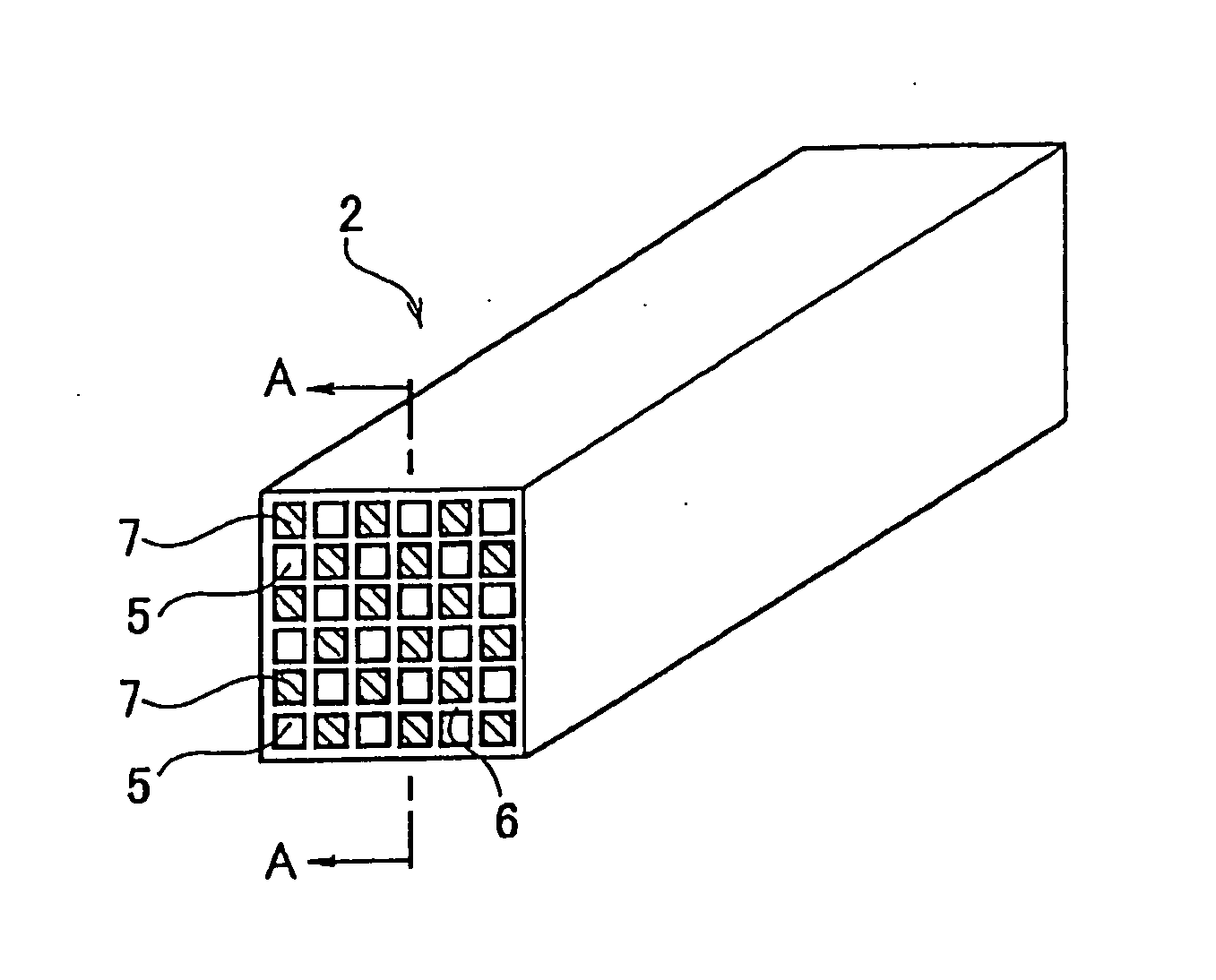
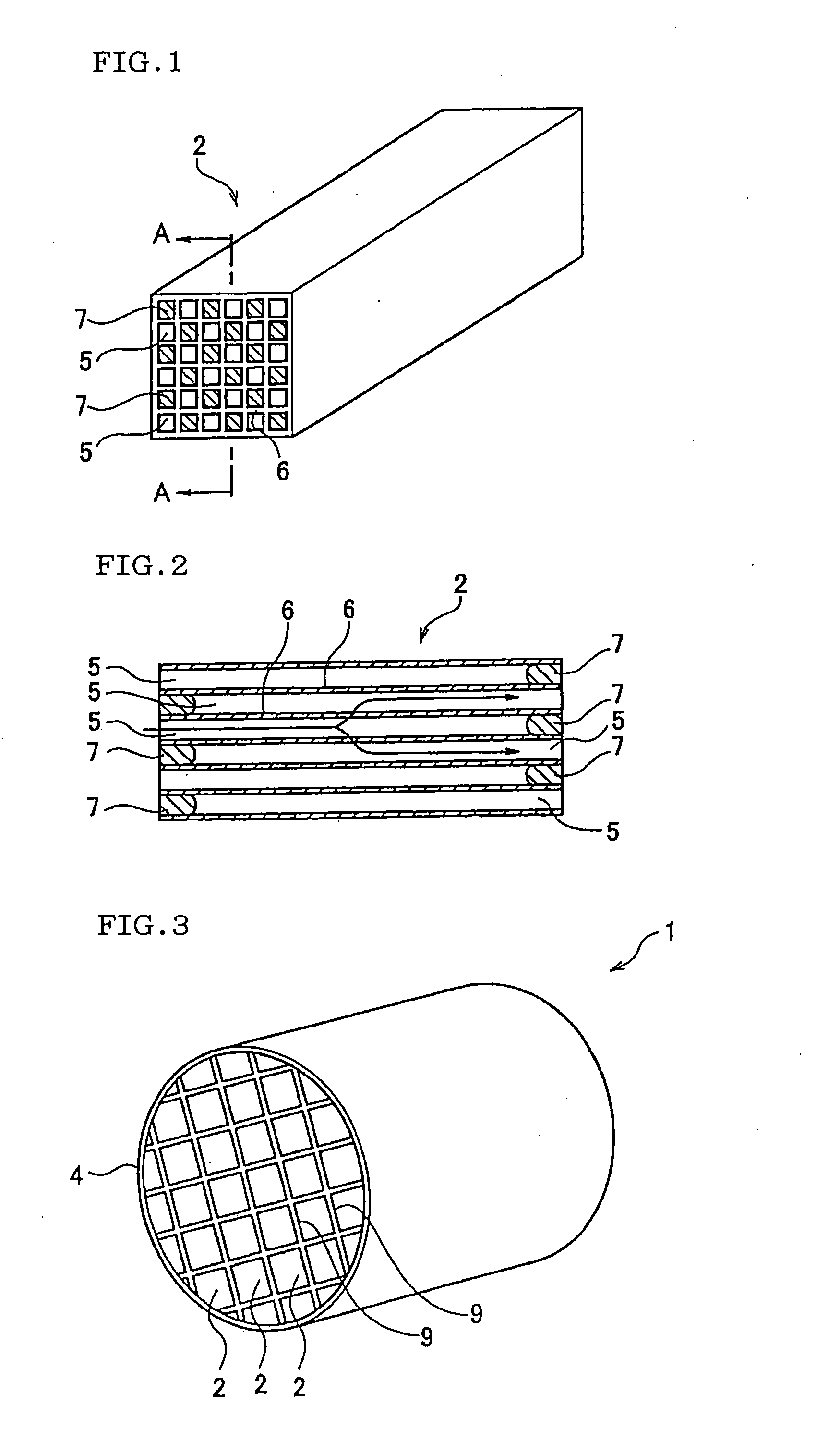
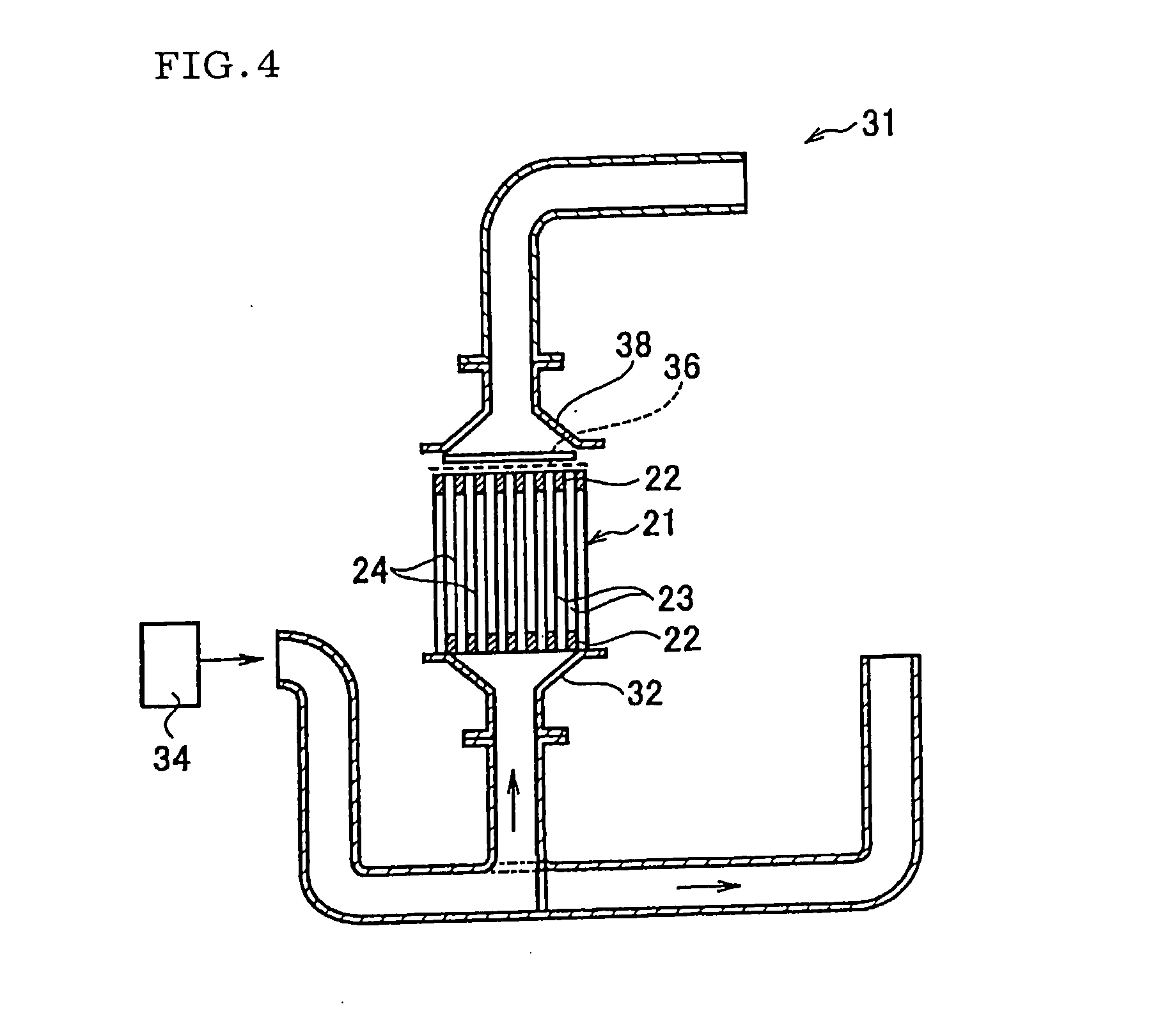
TECHNICAL FIELD [0001] The present invention relates to a method for producing a honeycomb structure which can be used for various kinds of filters or the like. In particular, the present invention relates to a method for producing a honeycomb structure, the method being capable of suppressing defects or deformation upon forming and improving a yield. BACKGROUND ART [0002] Among various filters, for example, a DPF (diesel particulate filter) is a filter used for trapping and removing particulates contained in exhaust gas from a diesel engine or the like and is incorporated into an exhaust gas system of a diesel engine for use. The filter such as a DPF is produced by bonding a plurality of honeycomb structures (honeycomb segment) with a honeycomb structure being one unit (honeycomb segment). [0003]FIGS. 1 and 2 show a honeycomb structure as one unit (honeycomb segment) to be used for such a DPF. As shown in FIGS. 1 and 2, the honeycomb structure 2 is formed in a cylindrical shape hav...

Claims


Application Information

Patent Timeline
IPC IPC(8): C04B35/64C04B33/36C04B35/195C04B35/565C04B38/00
CPCC04B35/195C04B35/565C04B35/6263C04B35/62635C04B35/62655C04B38/0006C04B2235/3217C04B2235/3218C04B2235/3418C04B2235/3445C04B2235/349C04B2235/428C04B2235/5436C04B2235/6021C04B2235/77C04B2235/80C04B38/0074C04B38/0645C04B38/08C04B2103/0051C04B35/00C04B38/0067B01D39/20B01D46/00
Inventor KANEDA, ATSUSHIICHIKAWA, SHUICHI
Owner NGK INSULATORS LTD
Learn More