Image processing device, focal plane distortion component calculation method, image processing program, and recording medium

a focal plane distortion and component calculation technology, applied in closed circuit television systems, color television details, television systems, etc., can solve the problems of inability to apply post-processing, inability to improve and inability to accurately calculate shaking. the effect of improving the quality of frame image data

Inactive Publication Date: 2010-08-26
SONY CORP
View PDF11 Cites 58 Cited by
  • Summary
  • Abstract
  • Description
  • Claims
  • Application Information

AI Technical Summary

Benefits of technology

[0014]According to the above configurations, various types of processing for improving quality of frame image data can be carried out based on the focal plane distortion component calculated from the motion vector, thereby realizing an image processing device, a focal plane distortion component calculation method, an image processing program, and a recording medium storing the image processing program, capable of improving quality of frame image data.

Problems solved by technology

Also, the method described in Japanese Unexamined Patent Application Publication No. 2008-78808 calls for dividing of the imaging device, and accordingly is not applicable to post-processing.
However, the frame image data includes focal plane distortion corresponding to the shaking of the imaging apparatus, as described above.
This has led to a problem wherein high-precision calculation of shaking is incalculable due to the effects of the focal plane distortion on the motion vectors, and consequently efforts to improve the quality of frame image data have not advanced.

Method used


Image

  • Image processing device, focal plane distortion component calculation method, image processing program, and recording medium
  • Image processing device, focal plane distortion component calculation method, image processing program, and recording medium
  • Image processing device, focal plane distortion component calculation method, image processing program, and recording medium

Examples


first embodiment

1. First Embodiment

1-1. Overall Configuration

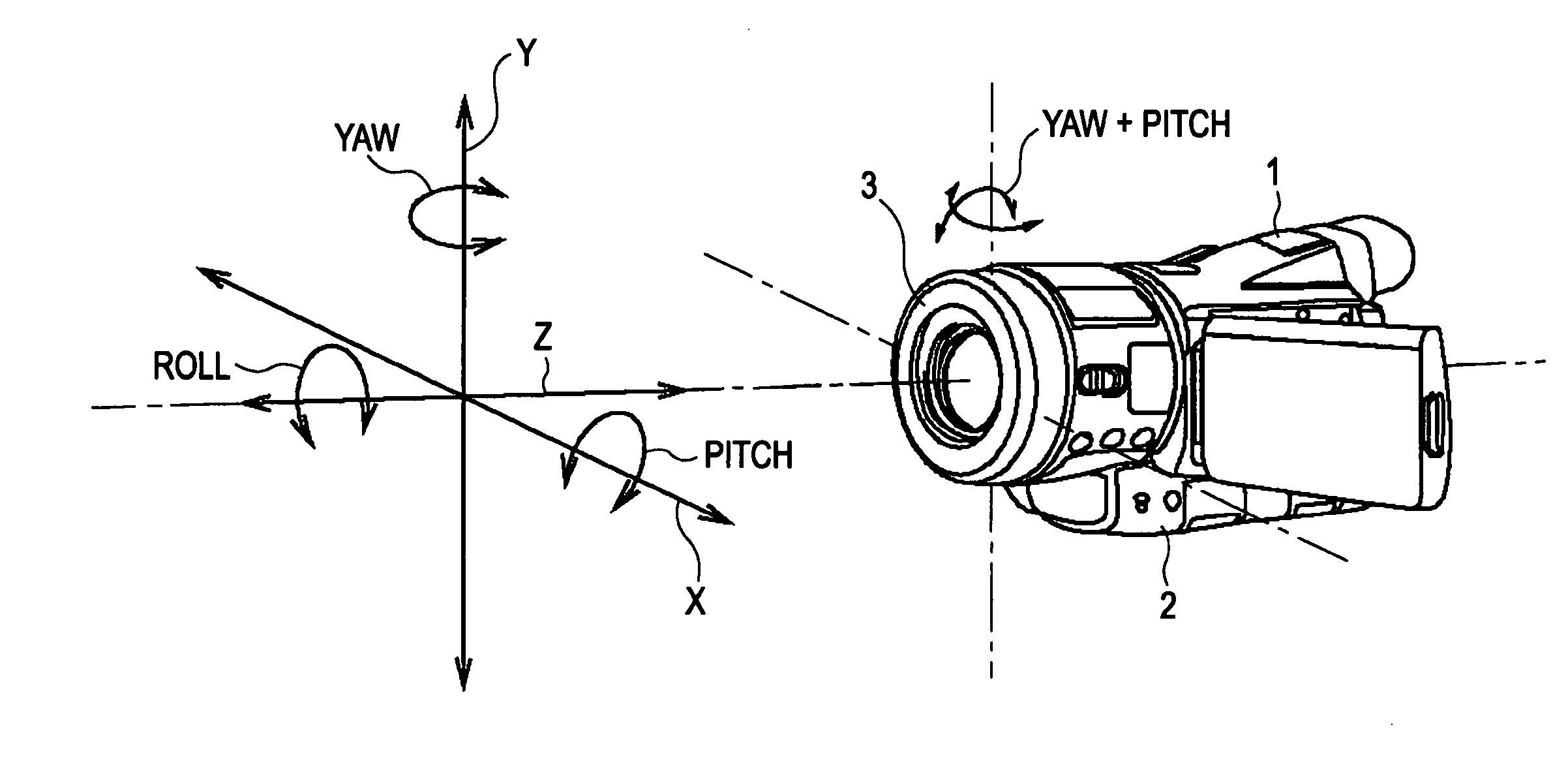
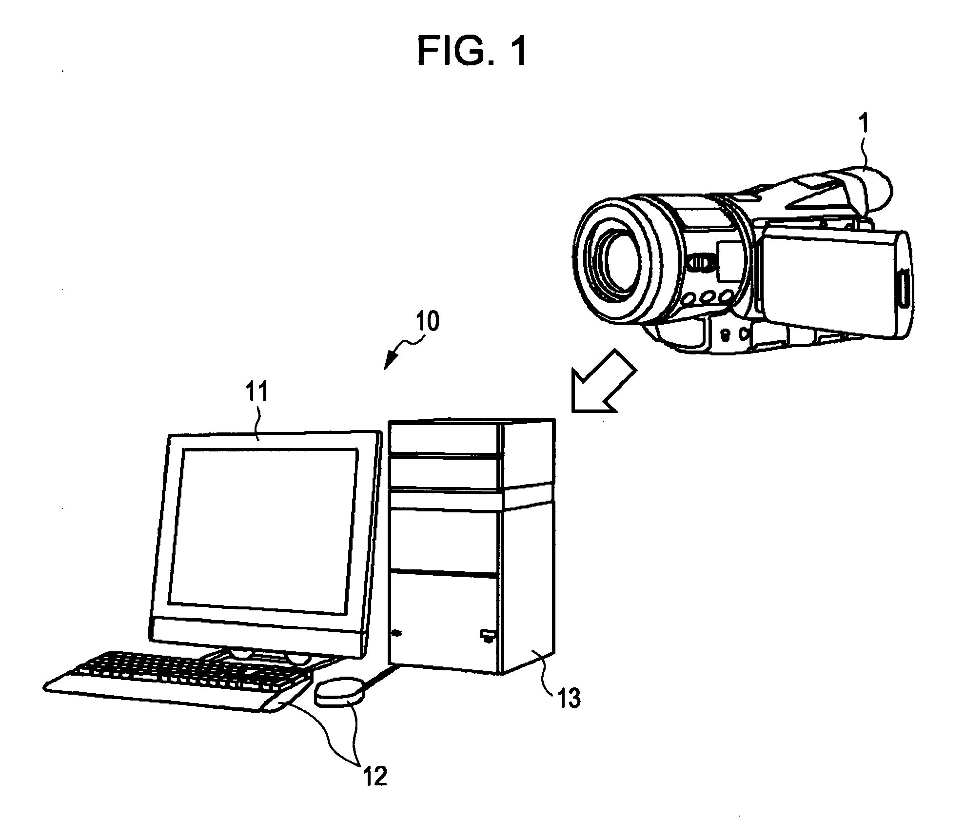
[0049]As shown in FIG. 1, an image processing terminal 10 is configured having a monitor unit 11, an operating unit 12, and an image processing unit 13. The image processing terminal 10 supplies frame image data supplied from a camcorder 1 to the image processing unit 13. The image processing unit 13 detects a global motion vector GMV from the frame image data making up a frame image. This global motion vector GMV represents the motion vector of the entire frame image.

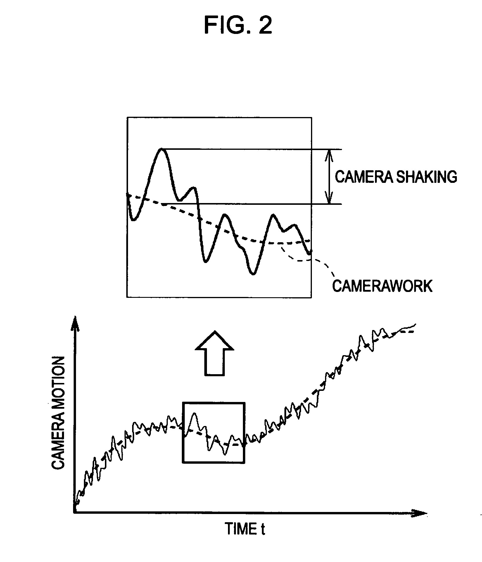
[0050]As described above, the global motion vector GMV includes, besides the amount of motion of the camera (hereinafter referred to as “camera motion”), a focal plane distortion component CF which is the amount of change of the focal plane distortion. Also, as shown in FIG. 2, the camera motion includes both movement which the user has intended (hereinafter referred to as “camerawork”), and shaking which is unintentional motion (hereinafter referred to as “camera shaking” o...

second embodiment

2. Second Embodiment

[0173]The second embodiment is illustrated in FIGS. 22 through 26B, in which portions corresponding to those in the first embodiment illustrated in FIGS. 1 through 21 are denoted with the same reference numerals, and accordingly redundant description of such portions will be omitted here.

[0174]The second embodiment differs from the first embodiment in that, as shown in FIG. 22, an image processing unit 113 corresponding to the image processing unit 13 has a trapezoidal distortion estimation unit 128. Also, with the second embodiment, the contents of motion detection processing, FP distortion correction amount calculation processing, and correction vector generating processing, differ from those in the first embodiment.

2-1. Motion Detection Processing

[0175]A motion detection unit 122 corresponding to the motion detection unit 22 in the first embodiment generates local motion vectors LMV and also reliability indices for the local motion vectors LMV. In the event th...

third embodiment

3. Third Embodiment

[0245]Portions of the third embodiment corresponding to those in the second embodiment illustrated in FIGS. 22 through 28 are denoted with the same reference numerals, and accordingly redundant description of such portions will be omitted here. While with the second embodiment, the correction vector generating unit 129 generates the correction vector Vc without changing the values of the component parameters following calculation of the trapezoidal distortion A, the third embodiment differs from the second embodiment in that the values of the component parameters are recalculated based on the trapezoidal distortion amount A.

3-1. Recalculation of Shaking Amount

[0246]As described above, with the first embodiment, the lens unit 3 of the camcorder 1 performs shaking correction by being driven in the yaw direction and pitch direction. Accordingly, angular change in the yaw direction and pitch direction is suppressed for the frame image data supplied to the image proces...


PUM


Abstract

An image processing device includes: a motion vector receiving unit configured to receive, from frame image data made up of frame images, motion vectors representing motion of the frame images; a modeling unit configured to model the motion vector, received from the motion vector receiving unit, to a component separation expression in which a camera motion component and a focal plane distortion component are separated, using component parameters respectively representing camera motion which is motion of a camera, and the amount in change in focal plane distortion; and a component calculation unit configured to calculate the component parameters used in the component separation expression, thereby calculating the focal plane distortion component in the motion vector.

Description

CROSS-REFERENCE TO RELATED APPLICATION[0001]The present application claims priority from Japanese Patent Application No. JP 2009-036897 filed in the Japanese Patent Office on Feb. 19, 2009, the entire content of which is incorporated herein by reference.BACKGROUND OF THE INVENTION[0002]1. Field of the Invention[0003]The present invention relates to an image processing device, a focal plane distortion component calculation method, an image processing program, and a recording medium, which are suitably applied to an image processing device for editing frame image data imaged with an imaging apparatus, for example.[0004]2. Description of the Related Art[0005]Heretofore, imaging apparatuses have widely employed an arrangement to correct camera shaking due to movement of the hands of the user holding the imaging apparatus, wherein sensors such as acceleration sensors are provided to the imaging apparatus, and optical parts such as lenses are moved so as to cancel out the movement due to ...

Claims


Application Information

Patent Timeline
Patent Type & Authority Applications(United States)
IPC IPC(8): H04N5/228
CPCH04N5/23248H04N23/68
Inventor OGAWA, NOBUHIRO
Owner SONY CORP
Why Eureka
Try Eureka