Light source device, optical device, and liquid-crystal display device

Inactive Publication Date: 2006-11-07
SEIKO EPSON CORP
View PDF71 Cites 59 Cited by
  • Summary
  • Abstract
  • Description
  • Claims
  • Application Information

AI Technical Summary

Benefits of technology

[0012]An object of the present invention, which was perfected in view of the above-described situation, is to provide a light source structure in which a plurality of point light sources are arranged in a planar configuration and which is suitable for miniaturization. Another object of the pr

Problems solved by technology

The above-described prior art, however, involves using a lamp as the light source, and is limited in the degree to which the size of the light source as such can be reduced.
It is thus difficult to reduce the size of the projector as a whole.
Light-emitting elements and other miniature light-emitting devices are substantially point light sources, and i

Method used


Image

  • Light source device, optical device, and liquid-crystal display device
  • Light source device, optical device, and liquid-crystal display device
  • Light source device, optical device, and liquid-crystal display device

Examples


Example

Embodiment 1

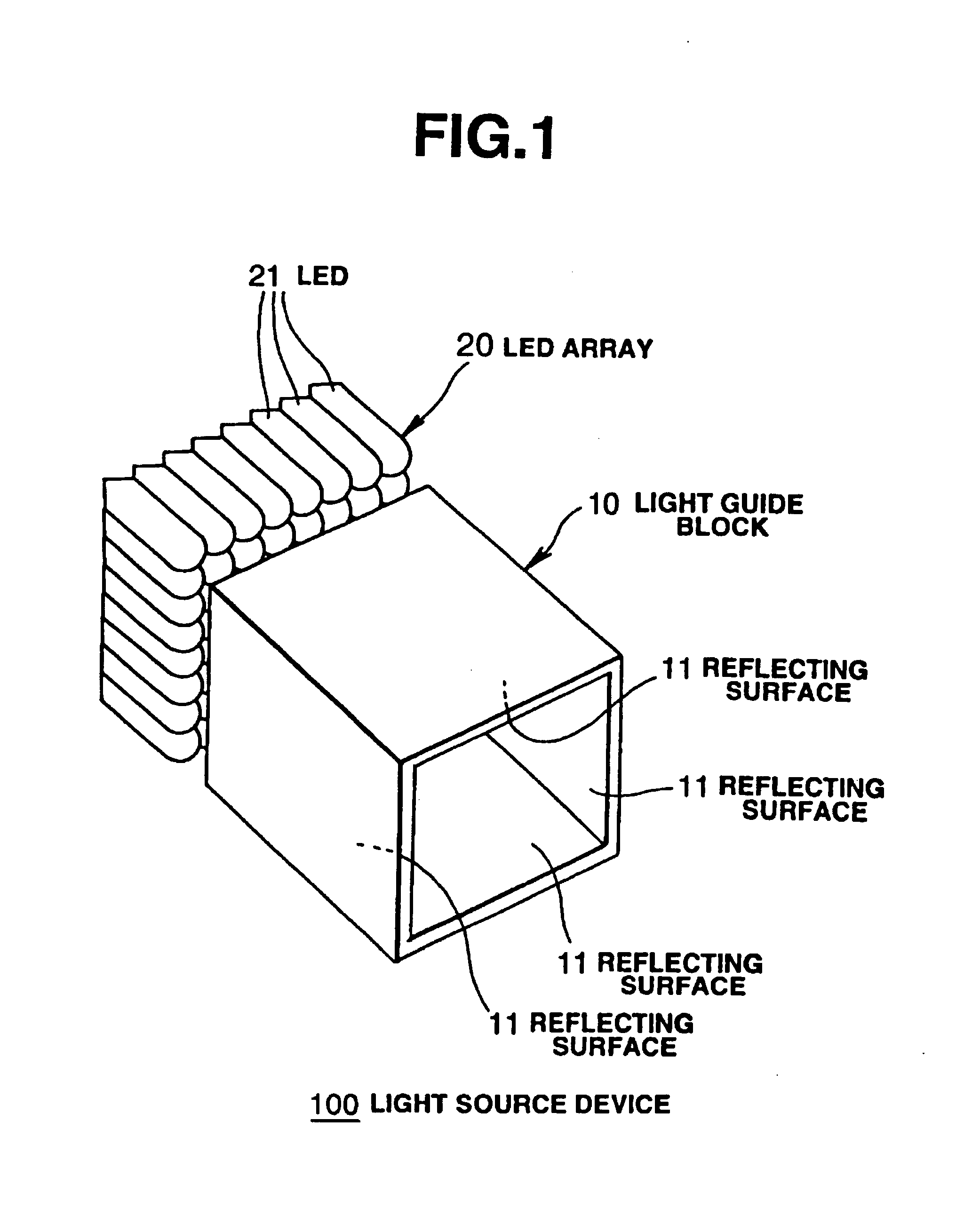
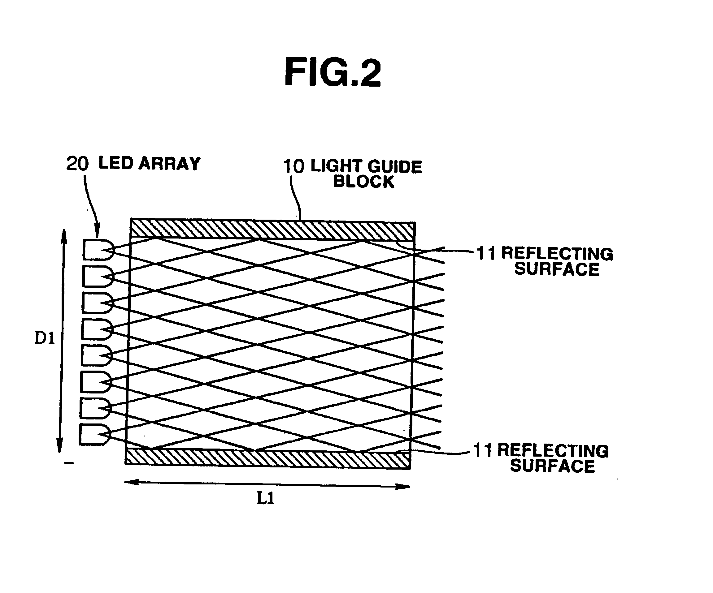
[0058]Embodiment 1 of the present invention relates to a light source device. FIG. 1 depicts a perspective view of a light source device 100 according to the embodiment. FIG. 2 is a cross section obtained by cutting the light source device 100 along its optical axis. The light source device 100 comprises a light-guiding block 10 and an LED (light-emitting diode) array 20.

[0059]The light-guiding block 10 is a hollow prismatic structure formed from a plurality of (four) wall surfaces. The inner walls thereof form reflective surfaces 11 capable of reflecting light. The light-guiding block 10 may, for example, be obtained by bonding together four mirrors that have the same size as a wall surface and that are placed opposite each other. It is also possible to form the block by bonding four panels obtained by vapor depositing thin aluminum metal films or other films on resin panels or the like, or by laminating reflective films with an adhesive. In any type of construction, th...

Example

Embodiment 2

[0071]Embodiment 2 of the present invention relates to a miniature projection-type liquid-crystal display device in which the light source device described with reference to embodiment 1 can be used. FIG. 4 is a block diagram of the optical system for the projection-type liquid-crystal display device 300 of the present embodiment.

[0072]The projection-type liquid-crystal display device 300 comprises a light source device 100, a liquid-crystal display element 30, a projection lens 31, and a screen 32 in a housing 33, as shown in FIG. 4. The light source device 100 is the same as that used in embodiment 1 above. The light source device 100 emits white light. The liquid-crystal display element 30 is so configured as to allow passage or blockage of light in individual pixels to be controlled in accordance with a drive signal (not shown). Specifically, the liquid-crystal display element 30 receives light emitted by the light source device 100 and is capable of modulating light...

Example

Embodiment 3

[0080]Embodiment 3 of the present invention will be described with reference to FIGS. 6 and 7.

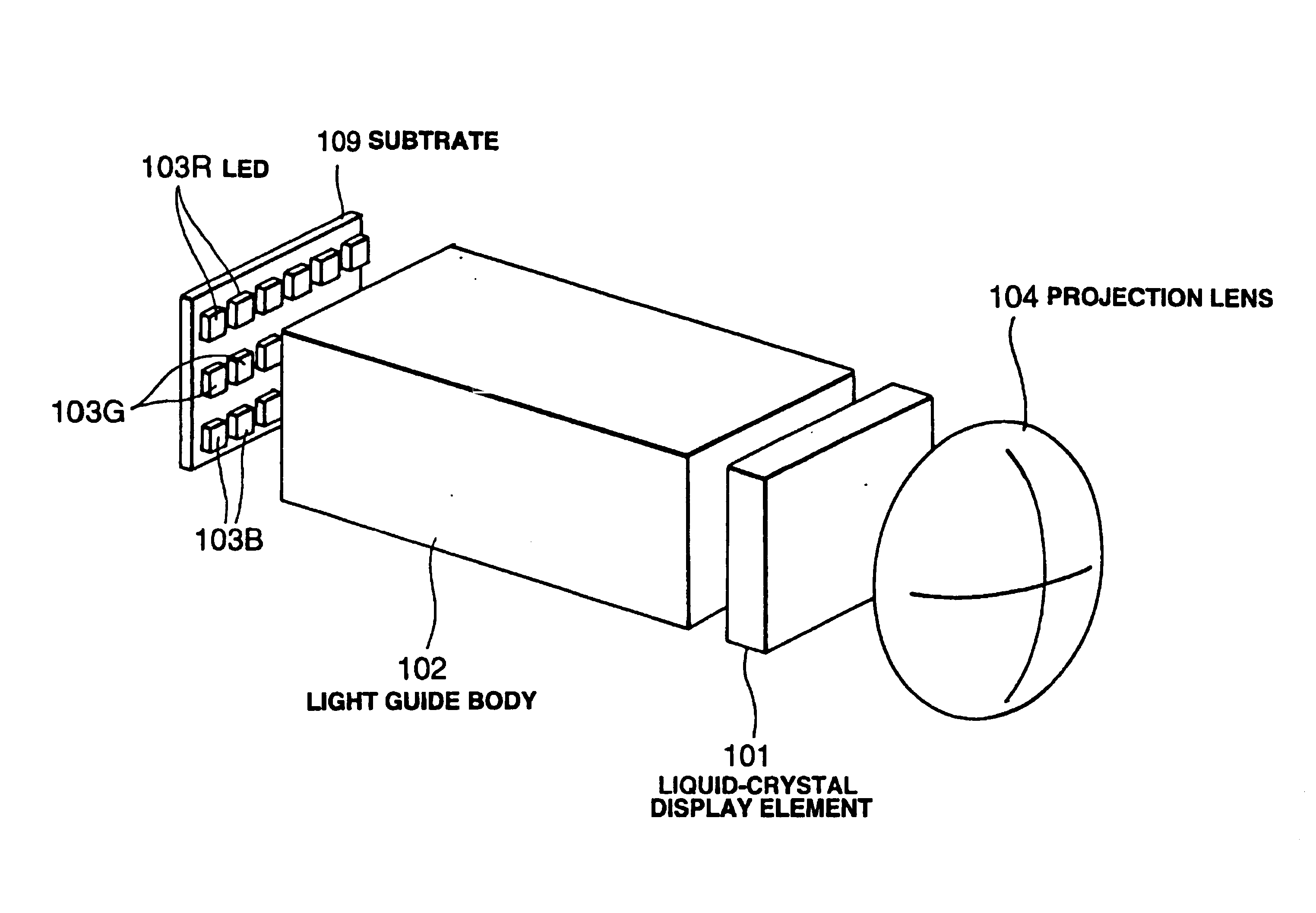
[0081]Light-emitting diodes (LEDs) 103 serving as point light sources are arranged in a planar arrangement, that is, in two dimensions, facing an end face (light-receiving end face) of a light guide body 102 (an acrylic resin square bar). The diodes form a separate entity from this light guide body 102. A liquid-crystal display element 101 is disposed facing the other end face (light-emitting end face) of the light guide body 102. Light emitted by the light-emitting end face of the light guide body 102 strikes the liquid-crystal display element 101. The image displayed by the liquid-crystal display element 101 is magnified by a projection lens 104 and is projected onto a screen 105.

[0082]The display region of the liquid-crystal display element 101 measures, for example, 10.2 mm×7.6 mm (0.5 inch diagonally), has a color filter for each pixel, and is capable of color display.

[0083...


PUM


Abstract

A light source device, comprising a light guide block that is provided with an inner wall capable of reflecting light and is shaped as a hollow component to form a light guide, and a point light source array that is located opposite one end face of the light guide block and is capable of emitting light into the light guide.

Description

[0001]This is a Division of application Ser. No. 09 / 485,155 filed Feb. 4, 2000, now U.S. Pat. No. 6,547,400. The entire disclosure of the prior application(s) is hereby incorporated by reference herein in its entirety.BACKGROUND OF THE INVENTION[0002]1. Field of the Invention[0003]The present invention relates to a projection-type liquid-crystal display device such as a light source device used in a projector, and particularly to a compact light source device suitable for use in a compact projector.[0004]2. Description of the Related Art[0005]In conventional practice, projectors in which images on liquid-crystal display elements are magnified, projected, and displayed are configured such that a single liquid-crystal display element is illuminated by a metal halide lamp from behind, and the image displayed by the liquid-crystal display element is magnified and projected by a projection lens.[0006]For example, Japanese Unexamined Patent Applications (Kokai) 62-237485, 3-75737, and 8-1...

Claims


Application Information

Patent Timeline
IPC IPC(8): G03B21/26G03B21/14G03B21/28G09G3/14G09G3/32G09F9/00F21V8/00G02B6/00G02B27/00G02F1/13G02F1/1335G02F1/13357H04N5/74H04N9/31
CPCG02B6/005G02B6/0068G02B6/0096G02F1/133603G02F1/133605G03B33/10H04N9/3105H04N9/3155H04N9/3164H04N9/3197G03B21/2033G03B21/204G03B21/208G02B6/0018G02B6/0073G02F1/133524G02F2001/133614G02F2001/133622H04N5/7441G02F1/133614G02F1/133622G02F1/133621
Inventor YOKOYAMA, OSAMU
Owner SEIKO EPSON CORP
Why Eureka
Try Eureka