Displacement encoder including phosphor illumination source

a technology of displacement encoder and phosphor illumination source, which is applied in the direction of measuring devices, converting sensor output optically, instruments, etc., can solve the problems of preventing the configuration of displacement encoders from being made more compact along the optical axis, and reducing the accuracy of displacement signals, so as to facilitate compact devices

Active Publication Date: 2012-01-10
MITUTOYO CORP
View PDF47 Cites 18 Cited by
  • Summary
  • Abstract
  • Description
  • Claims
  • Application Information

AI Technical Summary

Benefits of technology

[0006]The present invention is directed to improved displacement encoder configurations that provide improved combinations of compact size, robustness, range-to-resolution ratio, high resolution, and fabrication and assembly cost.
[0008]In accordance with one embodiment of the present invention, uniform light intensity is achieved without the use of a lens, by utilizing a primary light source to excite and saturate a phosphor area which then provides uniform illumination to a scale pattern. In one specific embodiment, the primary light source may provide non-uniform primary radiation that approximately saturates an area of uniformly distributed phosphor that absorbs the primary radiation at a first wavelength, the saturated phosphor then providing a “secondary” phosphor radiation at a second wavelength that illuminates the scale with a relatively uniform intensity to produce a scale pattern “image” (e.g., a shadow image) that is sensed by the photodetector. Due to saturation of the phosphor, the uniformity of the intensity of the secondary radiation may be similar to the uniformity of the saturated volume of the phosphor. Uniform illumination intensity may therefore be economically provided over a wide area with relatively few components, in a configuration that minimizes the path length and encoder size along a direction normal to the plane of the scale pattern. Other advantages include the ability to match the phosphor wavelength to the maximum sensitivity of the photodetector (e.g., for better signal-to-noise ratio and energy efficiency); patterning the phosphor to provide an economical source grating for self imaging type displacement encoders; and using the phosphor to provide diffuse illumination in applications where such is more desirable than directional illumination of the type typically provided by primary radiation sources (e.g., LEDs, laser diodes, etc.).
[0009]It will be appreciated that the intensity uniformity provided by the phosphor is improved over that obtained directly from a primary radiation source (e.g., a LED primary source, an interposed diffuser, etc.). In addition, the improved uniformity is achieved along a very short optical path. In other words, the saturated phosphor used in combination with a high divergence primary light source results in a configuration with a large illumination area and a very short optical path, which is desirable for achieving a more compact encoder configuration.
[0012]In some embodiments an absolute track detector portion may be configured with individual photodetector areas that have a Y direction edge-to-edge dimension YDETABS along a Y direction that is perpendicular to a measuring axis direction, and these photodetector areas may be configured to spatially filter their received spatially modulated light pattern and output a plurality of respective position indicating signals that have respective spatial phases. In one embodiment, the absolute track pattern comprises geometrically congruent subtrack portions that extend along the measuring axis direction, and the geometrically congruent subtrack portions are arranged such that if one of the geometrically congruent portions is translated along the Y axis direction by the dimension YDETABS, then the geometrically congruent portions will nominally coincide. The geometrically congruent subtrack portions may furthermore be configured such that they are separated along the Y direction by a dimension YCENT that is less than YDETABS, and the geometrically congruent subtrack portions may each have a Y direction dimension YTOL, such that the dimensional quantity [YCENT+2(YTOL)] is greater than YDETABS. Thus, the detector portion for sensing the absolute track may be narrower than the absolute track pattern along the Y direction, but because the ends of the photodetectors are each nominally located over geometrically congruent subtrack portions (to sense geometrically congruent light patterns), the detected signal is not sensitive to misalignment of the detector portion along the Y direction. It will be appreciated that a narrower detector portion is more economical, and may also facilitate a compact device. In some such embodiments the absolute scale pattern may have a width less than 3.0 millimeters and still be used to provide a desirable range-to-resolution ratio in an economical absolute encoder configuration.

Problems solved by technology

However, illumination non-uniformity may cause extraneous intensity variations within the spatially modulated light pattern on the photodetector, such that the accuracy of the displacement signal is degraded.
However, the required length of an optical path including such elements (e.g., a lens) prevents the encoder configuration from being made more compact along the optical axis, particularly as the area of the scale pattern that is included in the optical path is increased.

Method used


Image

  • Displacement encoder including phosphor illumination source
  • Displacement encoder including phosphor illumination source
  • Displacement encoder including phosphor illumination source

Examples


first embodiment

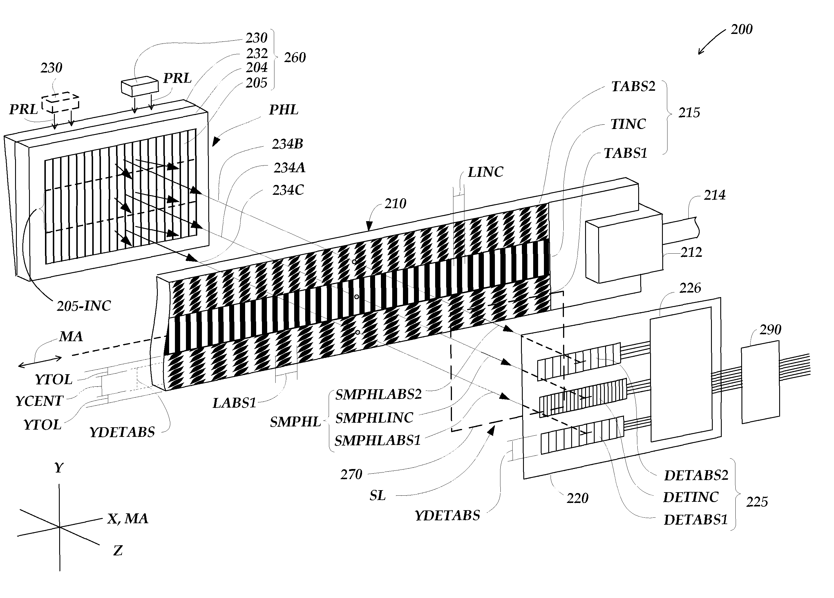
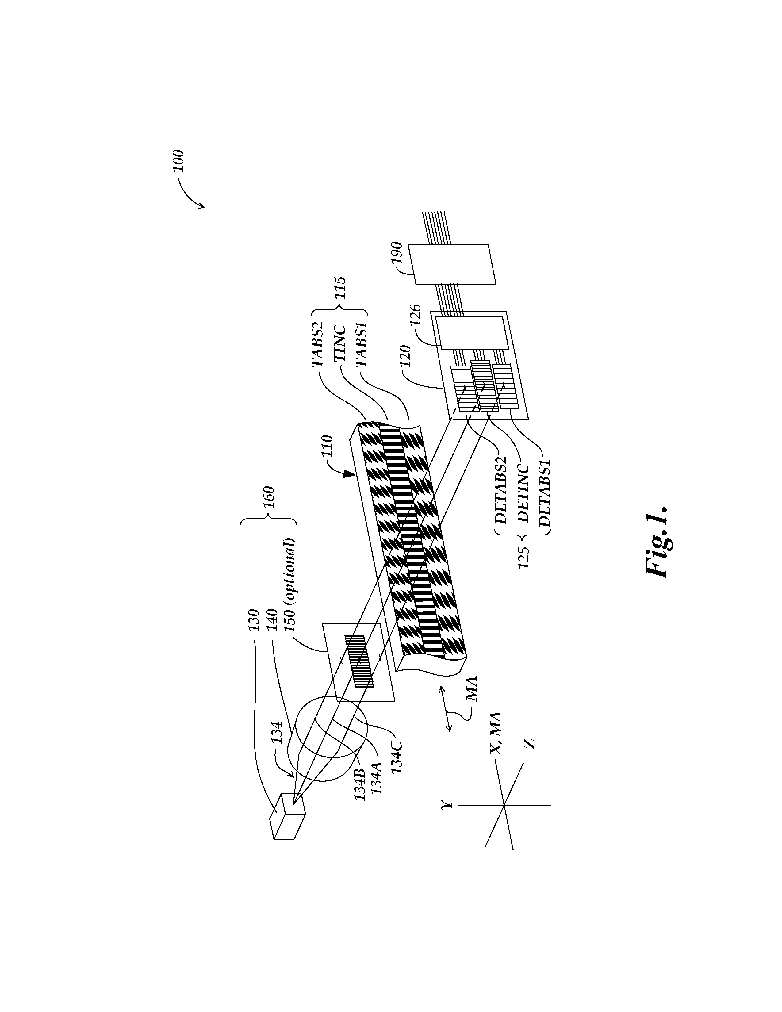
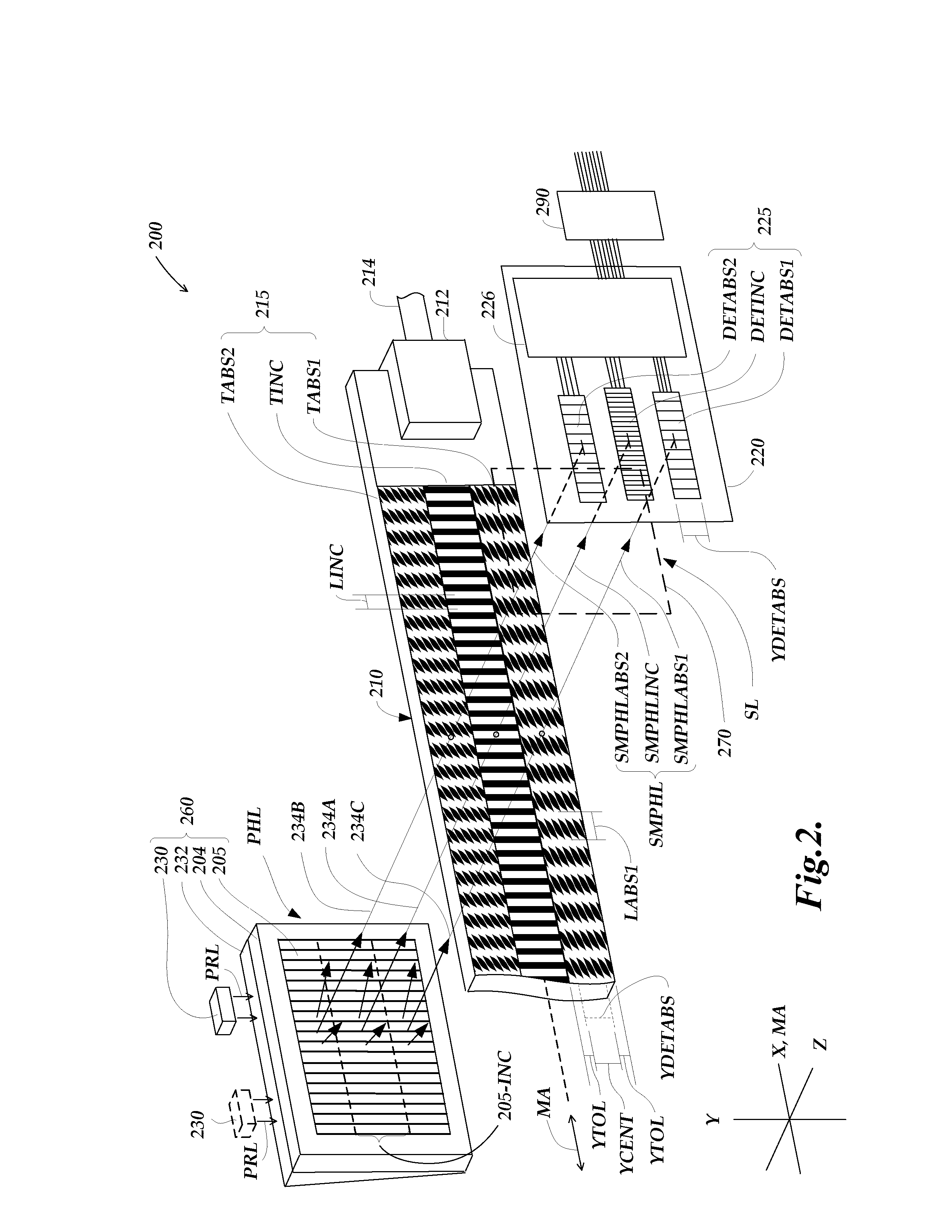
[0031]FIG. 2 is a partially schematic exploded diagram of an encoder configuration 200 utilizing a light source that includes a phosphor to provide illumination to a scale pattern that produces a corresponding spatially modulated light pattern on a detector in accordance with this invention. Except for the use of the phosphor to enhance the illumination uniformity and eliminate the requirement for an illumination lens, the components and operating principles of the encoder configuration 200 may be approximately similar to those of the encoder configuration 100 of FIG. 1, and may generally be understood by analogy. For example, 2XX series numbers in FIG. 2 that have the same “XX” suffix as 1XX series numbers in FIG. 1 may designate similar or identical elements, which may function similarly, except as otherwise described or implied below.

[0032]As shown in FIG. 2, the encoder configuration 200 includes a scale element 210, detector electronics 220 which is connected to signal generati...

second embodiment

[0047]FIG. 3 is a diagram of a cross-sectional end view of an encoder configuration 300 utilizing a light source that includes a phosphor area to provide illumination to a scale pattern, and FIGS. 4A-4C are diagrams of top and bottom views of selected components at different layers within the encoder configuration 300 of FIG. 3, with alignment along the Y direction approximately maintained throughout all these figures. In one embodiment, the encoder configuration 300 may be similar to the encoder configuration 200 of FIG. 2, and elements having 3XX reference numbers may generally be analogous to elements having 2XX reference numbers in FIG. 2, and may generally be similarly understood and configured in an analogous manner, unless otherwise indicated by description or context. As shown in FIG. 3, the encoder configuration 300 includes a scale member 310 including a scale pattern 315, a circuit assembly 395 (e.g., a printed circuit board and associated signal processing circuitry) inc...

third embodiment

[0054]FIG. 5 is a diagram of a cross-sectional end view of an encoder configuration 500 utilizing a light source that includes a phosphor area to provide illumination of a scale pattern, and FIGS. 6A-6D are diagrams of top and bottom views of selected components at different layers within the encoder configuration of FIG. 5, with alignment along the Y direction approximately maintained throughout all these figures. In one embodiment, certain of the components of the encoder configuration 500 may be similar to their counterparts in the encoder configuration 300 of FIGS. 3 and 4A-4C, and elements having 5XX reference numbers may generally be analogous to elements having 3XX reference numbers in FIGS. 3 and 4A-4C, and may generally be similarly understood and configured in an analogous manner, unless otherwise indicated by description or context. As shown in FIG. 5, the encoder configuration 500 includes a scale member 510 including a scale pattern 515, a circuit assembly 595 (e.g., a ...


PUM


Abstract

A position sensing optical encoder includes an illumination source that operates by providing primary radiation having a first level of intensity uniformity to saturate at least a portion of a relatively broad phosphor area including uniformly distributed phosphor. The phosphor area absorbs the primary radiation and emits phosphor radiation to illuminate the encoder scale pattern. The scale pattern spatially modulates the phosphor light, and the spatially modulated pattern of phosphor light is sensed by a photodetector arrangement. Due at least partially to saturation of the phosphor, the phosphor light has a second level of phosphor light intensity uniformity that is more uniform than the first level of primary light intensity uniformity, which enhances the encoder accuracy. The uniform phosphor illumination intensity is economically provided over a broad area with few components and minimized optical path length, particularly for path length perpendicular to the scale.

Description

FIELD OF THE INVENTION[0001]The invention relates generally to precision measurement instruments, and more particularly to a displacement encoder that utilizes a phosphor illumination source.BACKGROUND OF THE INVENTION[0002]Various optical displacement encoders are known that use a readhead having an optical arrangement that images a scale pattern to a photodetector arrangement in the readhead. The image of the scale pattern displaces in tandem with the scale member, and the movement or position of the displaced scale pattern image is detected with a photodetector arrangement. Conventional imaging, self-imaging (also called Talbot imaging), and / or shadow imaging may be used to provide the scale pattern image in various configurations.[0003]Optical encoders may utilize incremental or absolute position scale structures. An incremental position scale structure allows the displacement of a readhead relative to a scale to be determined by accumulating incremental units of displacement, s...

Claims


Application Information

Patent Timeline
Patent Type & Authority Patents(United States)
IPC IPC(8): G01B11/14G01D5/34
CPCG01D5/34715
Inventor KAPNER, DANIEL J.
Owner MITUTOYO CORP
Why Eureka
Try Eureka