[0023]If the secondary lens is mounted at the predetermined distance from the primary lens, then the virtual light source will be optically imaged on a predetermined
image plane which it is intended should be illuminated. If the light source is a flat Lambertian source, as is more or less the case with light-emitting diodes, then an
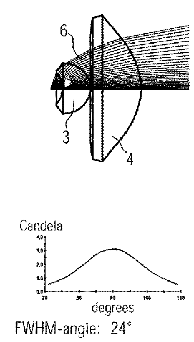
irradiance distribution according to the cos4 law results. Because of the small angle of emission of the
cone of light rays, the cos4 effect is negligible, so that a substantially uniform illumination intensity is obtained.
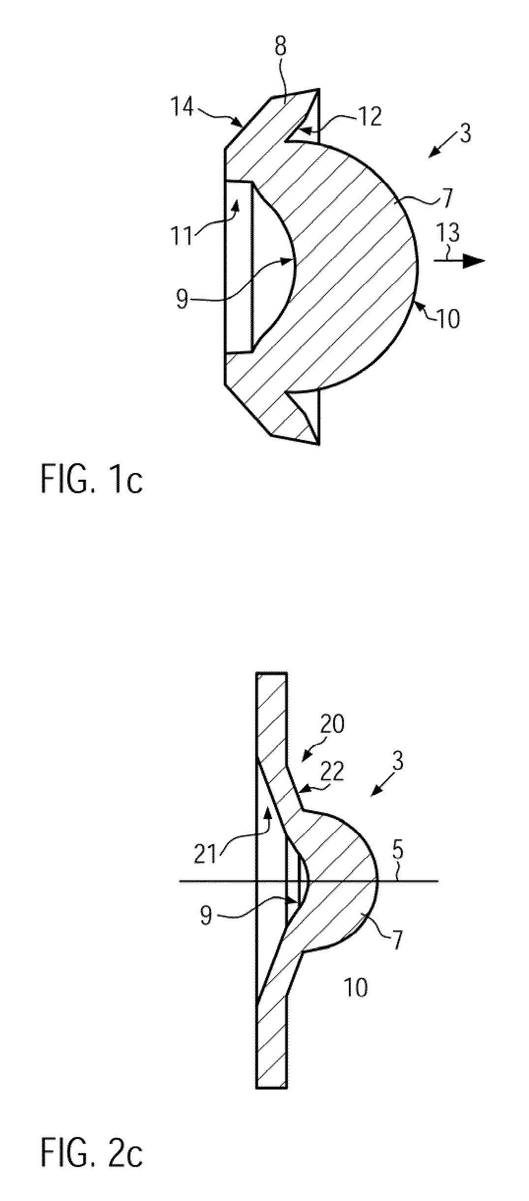
[0025]The primary lens is an aplanat. In the present disclosure, the term “aplanat” is used to describe a lens that is corrected aplanatically in a certain arrangement relative to the light source. By this means a small light source is imaged free from
coma and free from
spherical aberration. The
coma and the
spherical aberration are the dominant imaging errors in the case of lenses with a high aperture. Consequently, the primary lens generates an exact
virtual image of the light source. This exact
virtual image can accordingly be imaged by the secondary lens. The provision of an aplanat as primary lens leads to considerably better imaging of the light source than with a primary lens which is not aplanatic, since on the one hand the maximum possible concentration (bundling), and on the other hand uniform illumination, are obtained. The efficiency and the evenness of the illumination of the cone of light rays produced by the lighting device are therefore optimized.
[0027]The intermediate zone between the two “imaging extremes” represents a mixed state between these two images in which there is a
gradual transition from the sharply focused cone of light rays to a wider cone of light rays, with an increasingly strong gradient of
light intensity from the inside to the outside. A significant
advantage over conventional light source is that there is always a high
light intensity in the centre of the cone of light rays. This is a significant benefit since, in the case of known light sources with
variable angle of emission, because of geometrical effects there is generally for a certain area of the angle of emission a considerable reduction in
light intensity in the centre. Such a
dark spot is perceived as very disadvantageous by the
human eye. This is reliably prevented by making the primary lens an aplanat.
[0028]The lighting device is especially advantageous when a light-emitting
diode or a light source with similar properties to those of a light-emitting
diode is used, since in the imaging by means of an aplanat, the light intensity distribution of a Lambertian source, homogeneous over the
angular range, is imaged on to another
angular range. In this process the homogeneity of the light intensity distribution is maintained and, in the
optical imaging of the light source, the even illumination of the flat-surfaced emitting surface is imaged on the target.
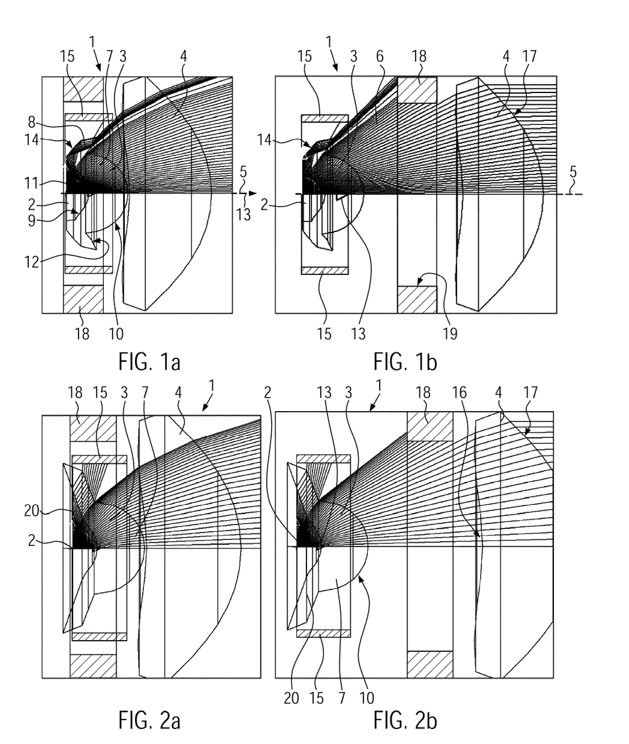
[0029]According to the second aspect of the present invention, the secondary lens is able to slide over a distance extending in a range in which the secondary lens does not cover the whole of the cone of light rays generated by the primary lens. It is true that this has the consequence that the efficiency and the overall
luminous flux of the light
ray concentration or beam emitted by the lighting device reduces since a portion of the light output is no longer captured by the secondary lens. However, in the case of such large distances between the primary lens and the secondary lens, in which the secondary lens does not cover the whole of the cone of light rays generated by the primary lens, there is a very strong concentration of the light
ray beam or bundle emitted by the lighting device, which makes the light intensity very high. It has been shown that, while the overall quantity of light of the cone of light rays reduces with increasing concentration, the light intensity remains constant, since essentially only the
solid angle areas
lying in the
peripheral zone are faded out by the increasing concentration. Because the secondary lens is able to slide in a range in which the cone of light rays produced by the primary lens is no longer captured completely, it is possible to focus extremely highly the cone of light rays emitted by the lighting device.

