Conversion of solar energy to electrical and/or heat energy

Inactive Publication Date: 2008-07-10
EDTEK INC
View PDF9 Cites 58 Cited by
  • Summary
  • Abstract
  • Description
  • Claims
  • Application Information

AI Technical Summary

Benefits of technology

[0013]The solar energy conversion system of the invention is unique because it converts solar to thermal energy in the form of hot water at useful temperatures while simultaneously converting solar power to electrical power at high efficiency. In the system of the invention, the concentra

Problems solved by technology

However, cost has always been an obstacle to its widespread use.
This approach requires large areas of expensive semi-conductor solar cells.
To date, these systems have been uncompetitive without cost subsidies of some sort.
In general, the prohibitive cost of solar energy systems has been primary due to the cost and the quantities required of the semi-c

Method used


Image

  • Conversion of solar energy to electrical and/or heat energy
  • Conversion of solar energy to electrical and/or heat energy
  • Conversion of solar energy to electrical and/or heat energy

Examples


Embodiment Construction

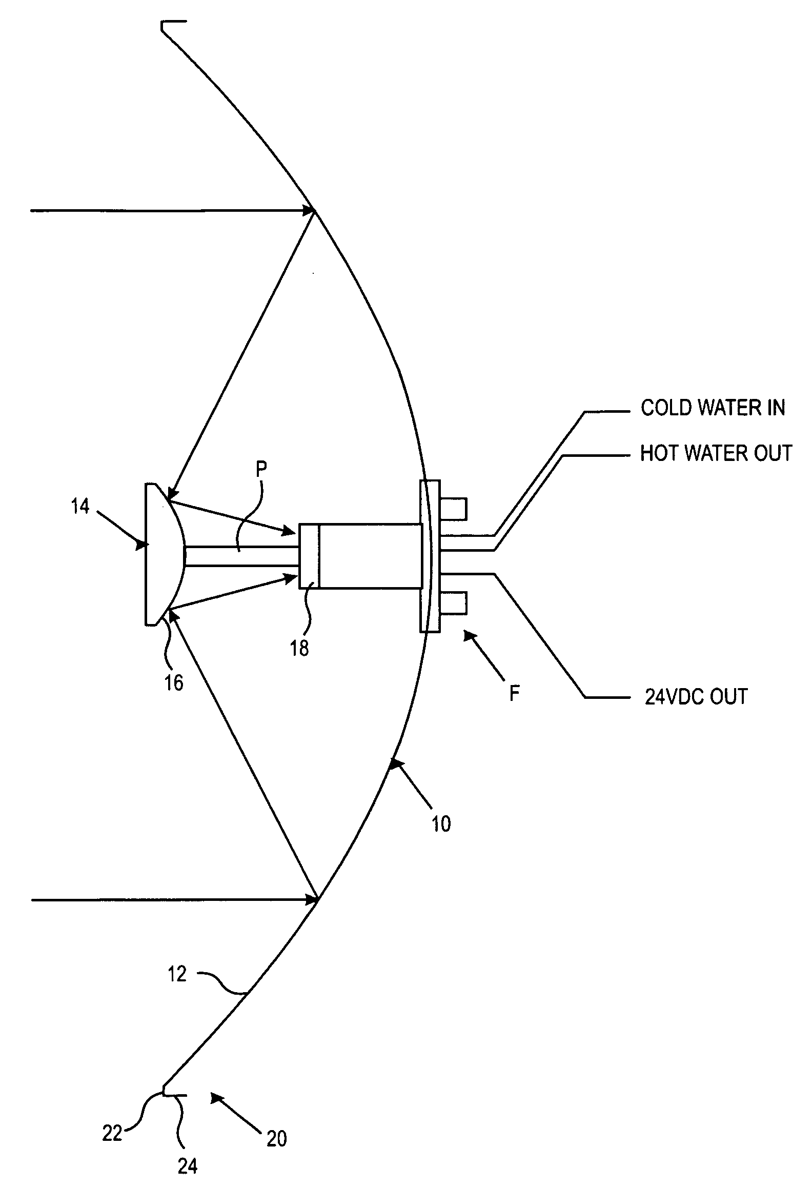
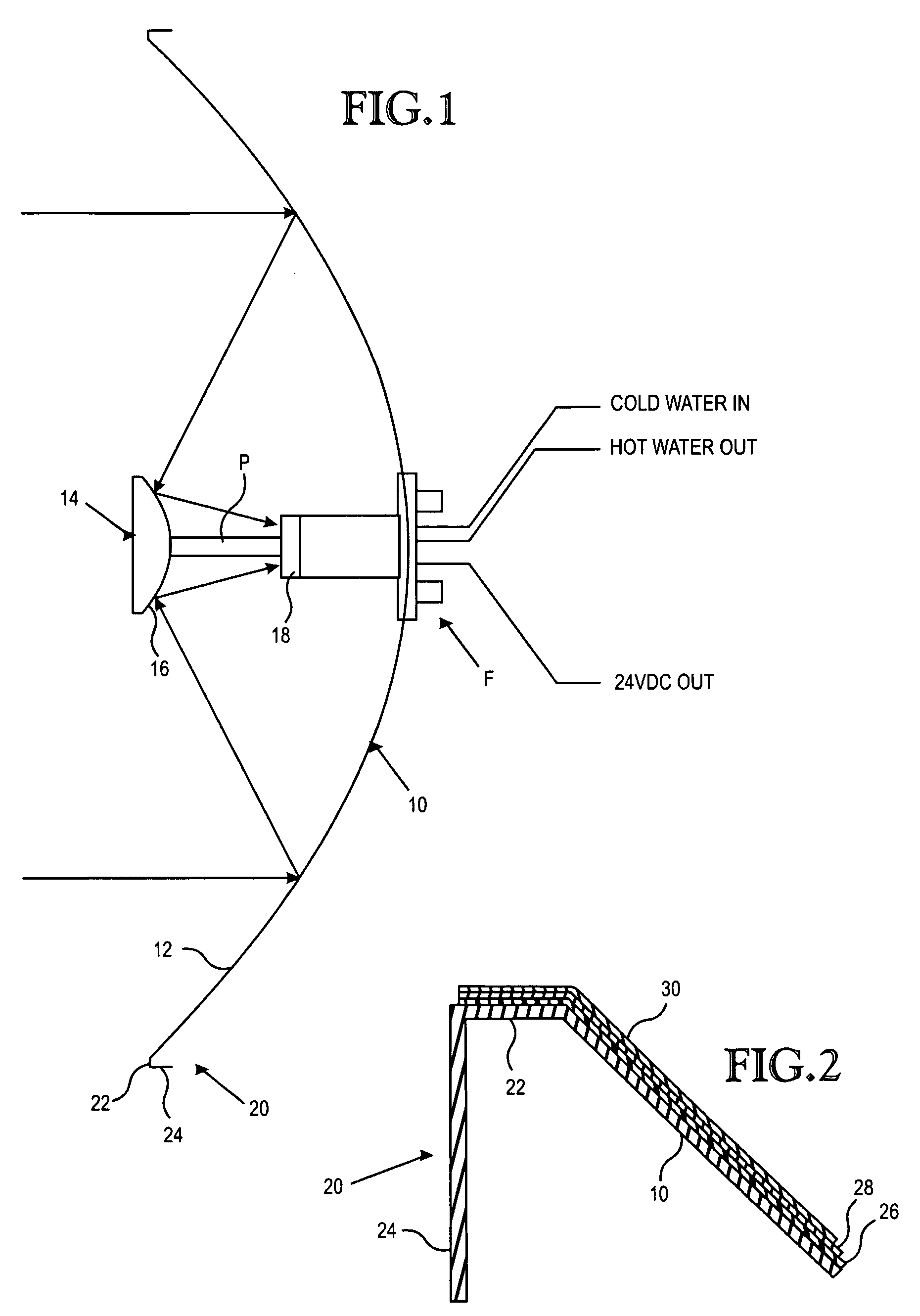
[0045]FIG. 1 is a schematic view of the optical components of the illustrated embodiment of the invention. It comprises a primary mirror 10, a secondary mirror 14 and an optical concentrator 18. Primary mirror 10 is a concave / convex dish that has a specular surface 12 on its concave side. Secondary mirror 14 is a concave / convex dish having a specular surface 16 on its convex side. The convex side 16 of mirror 14 confronts the concave side 12 of the mirror 10. The concave specular surface 12 is preferably parabolic and the specular surface 16 is generally hyperbolic. The substantially parabolic surface 12 is shaped to focus axially collimated sun rays to a focus point co-planar to its rim 20. This focal point is coincident with the virtual focal point of a generally hyperbolic specular surface 16 of the secondary mirror 14. Specular surface 16 is constructed and positioned to concentrate the solar energy that it receives from the primary mirror surface 12 and concentrate it onto an a...


PUM


Abstract

A parabolic primary mirror (10) has a concave specular surface (12) that is constructed and positioned to receive solar energy and focus it towards a focal point. A secondary mirror (14) having a convex specular surface (16) is constructed and positioned to receive focused solar energy from the primary mirror and focus it onto an annular receiver (18). The annular receiver (18) may include an annular array of optical elements (100) constructed to receive solar energy from the secondary specular surface (14) and focus it onto a ring of discreet areas. A ring of solar-to-electrical conversion units are positioned on the ring of discreet areas. A sun sensor that allows accurate solar tracking to keep mirror system aligned with the sun.

Description

TECHNICAL FIELD[0001]This invention relates to improvements in the conversion of solar energy to electrical and / or heat energy. More particularly, the present invention provides a system of mirrors and lenses / prisms for economically collecting solar energy and converting it to electrical and / or heat energy.BACKGROUND OF THE INVENTION[0002]Solar energy has been a desirable energy source for over thirty years. However, cost has always been an obstacle to its widespread use. The most familiar solar energy systems comprise an array of solar cells that cover enough area, or intercepts enough incident sunlight, to yield the desired amount of electrical power at relatively low conversion efficiencies of ten to fifteen percent (10%-15%). This approach requires large areas of expensive semi-conductor solar cells. To date, these systems have been uncompetitive without cost subsidies of some sort. In general, the prohibitive cost of solar energy systems has been primary due to the cost and the...

Claims


Application Information

Patent Timeline
IPC IPC(8): H01L31/042G02B5/10F24S23/30F24S23/70F24S23/71F24S23/79F24S50/20
CPCF24J2/18Y02E10/40Y02E10/52Y02E10/60H01L31/0547G02B19/0042G02B19/0023H02S40/44F24J2/405F24S23/79F24S50/60Y02E10/47H02S40/22
Inventor HORNE, WILLIAM E.MORGAN, MARK D.
Owner EDTEK INC
Why Eureka
Try Eureka