Two-dimensional surface normal slow-light photonic crystal waveguide optical phased array

a phased array and photonic crystal waveguide technology, applied in the direction of optical elements, cladded optical fibres, instruments, etc., can solve the problems of unachievable large angles and speeds by any current method, and achieve the effect of fast, large angle dynamic steering of multiple optical beams, and simplifying the process of optical beam steering

Active Publication Date: 2012-06-12
OMEGA OPTICS
View PDF6 Cites 14 Cited by
  • Summary
  • Abstract
  • Description
  • Claims
  • Application Information

AI Technical Summary

Benefits of technology

[0012]One embodiment of the invention provides a two dimensional optical phased array comprising an air core photonic crystal waveguide formed in a semiconductor material which has a high thermo-optic coefficient. The semiconducting material made up of the first dielectric constant consists of a top and a bottom flat surface and is optically transparent beyond 1100 nm wavelength. A triangular lattice of air holes is etched into the semiconducting material from the top surface to the bottom surface of the semiconducting material, forming a hexagonal close pack photonic crystal structure. A surface-normal photonic crystal waveguide is defined by forming a larger air hole at the center of the photonic crystal lattice from the top surface of the semiconducting material to the bottom surface of the semiconducting material. The air hole diameters, including the large central air hole and the periodicity of the air holes are controlled in order to generate a photonic bandgap in the wavelength range of interest. The high dielectric constant contrast between the semiconducting material and air facilitates the formation of a slow-light mode within the photonic bandgap which is characterized by a very large group index.
[0014]The primary objective of the invention is to simplify the process of optical beam steering by providing a compact two dimensional integrated surface normal slow-light photonic crystal waveguide array that can be integrated with heating electrodes and a holographic light coupler array to implement fast, large angle dynamic steering of multiple optical beams.
[0015]The second objective of the invention is to eliminate the need for precise layer by layer arrangement required in the conventional waveguide systems in order to generate the two dimensional array and to provide a one step manufacturing process for the device, thereby greatly simplifying its fabrication.
[0016]The third objective of the invention is to simplify light injection into the device by using a holographic fanout array. Controlled diffraction efficiencies of the holograms can provide uniform light intensities to each photonic crystal waveguide in the array.

Problems solved by technology

Such large angles and speeds are unachievable by any of the current methods.

Method used


Image

  • Two-dimensional surface normal slow-light photonic crystal waveguide optical phased array
  • Two-dimensional surface normal slow-light photonic crystal waveguide optical phased array
  • Two-dimensional surface normal slow-light photonic crystal waveguide optical phased array

Examples


Embodiment Construction

Detailed Description of the Invention

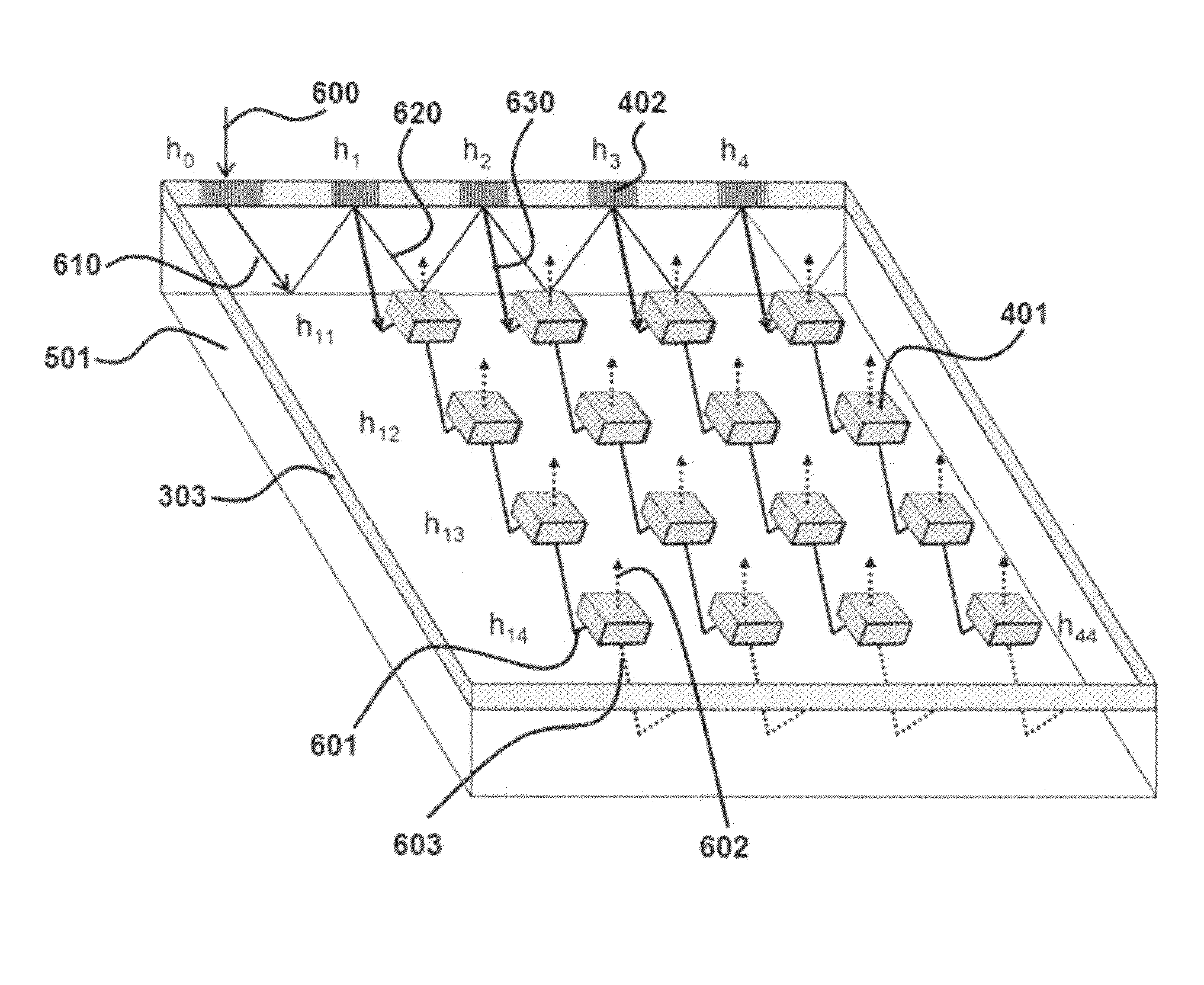
[0032]In accordance with a preferred embodiment of the present invention, a device for optical beam steering comprises: a two-dimensional array of surface normal photonic crystal waveguides, an input light coupler comprising a substrate wave guided (SWG) holographic fanout array, a photonic crystal waveguide taper, and heating metal electrodes. Light from a tunable laser source is coupled into the SWG. The SWG creates a two dimensional fanout array with uniform intensities at the outputs, which are coupled into the two dimensional photonic crystal waveguide array. Metal heating electrodes in each pixel change the refractive index of the material, thereby changing the group index, due to the dependence of group index (which is also a function of wavelength) on temperature. Thus, a group index contrast is achieved via temperature tuning, which thereby produces a large phase shift in the optical beam. The temperature change of each pixel is controll...


PUM


Abstract

Methods and devices for optical beam steering are disclosed including coupling a laser light into an apparatus comprising a first substrate; an array of air core photonic crystal waveguides; columnar members etched around each air core waveguide; a pair of metal electrodes around the columnar members; a trench around the pair of metal electrodes surrounding each air core photonic crystal waveguide; a second substrate coupled to the first substrate comprising electrical interconnection lines; and a holographic fanout array comprising a third substrate; a photopolymer film coated on the third substrate; a hologram written in the photopolymer film configured to couple the laser light into the third substrate; and an array of holograms recorded in the photopolymer film configured to couple a portion of the laser light into the waveguides; and passing a current through the electrodes to induce a refractive index change in the first substrate to control the phase of the portion of the laser light that passes through each waveguide. Other embodiments are described and claimed.

Description

BACKGROUND OF THE INVENTION[0001]1. Field of the Invention[0002]This invention relates generally to the field of optical beam steering systems, and more specifically to an apparatus and method for two dimensional optical beam steering for use in laser based radar systems.[0003]2. Background of the Invention[0004]Optical Phased Array (OPA) technology represents an enabling technology that makes possible simple, affordable, and lightweight laser beam steering with very precise stabilization, random access pointing, and programmable multiple simultaneous beams. Military applications include laser weapons, search and rescue, missile tracking, etc. Commercial side applications include laser printing, optical computing, etc. For all of the stated applications, an OPA technology is desired that exhibits high speed and large area scanning of laser beams covering wavelengths from the infrared to the ultraviolet. During the last decade, intensive efforts have been made to improve OPA performa...

Claims


Application Information

Patent Timeline
Patent Type & Authority Patents(United States)
IPC IPC(8): G02B6/34
CPCB82Y20/00G02B1/005G02B5/32G02B6/1225G02F1/2955G03H2001/0264G02F2202/32G03H1/0408G03H1/30
Inventor SUBBARAMAN, HARISHCHEN, RAY T
Owner OMEGA OPTICS
Why Eureka
Try Eureka