Substrate processing apparatus, substrate processing method, and substrate holding apparatus

a substrate and processing method technology, applied in the direction of transportation and packaging, liquid/solution decomposition chemical coating, cleaning using liquids, etc., can solve the problems of contamination of the substrate, water marks, and liquid being present near the substrate holder, so as to improve the rotational accuracy of the substrate, reduce the force applied by the rollers to the substrate, and improve the uniformity and stability of the process

Active Publication Date: 2006-10-19
EBARA CORP
View PDF12 Cites 57 Cited by
  • Summary
  • Abstract
  • Description
  • Claims
  • Application Information

AI Technical Summary

Benefits of technology

[0015] The present invention has been made in view of the above drawbacks. It is, therefore, a first object of the present invention to provide a substrate processing apparatus and a substrate processing method which can prevent a fluid such as a processing liquid from being scattered from a substrate and a substrate holder while cleaning and drying the substrate, and can eliminate the remaining fluid on the substrate holder and can also accelerate replacement of the fluid.
[0016] It is a second object of the present invention to provide a substrate processing apparatus and a substrate processing method which can equally dry upper and lower surfaces of the substrate by supplying a gas to the substrate, can also prevent water marks from being produced on the substrate, and can dry the substrate by rotating the substrate at a low rotational speed.
[0017] It is a third object of the present invention to provide a substrate processing apparatus and a substrate processing method which can improve a uniformity of a process on the surface of the substrate.

Problems solved by technology

However, in the conventional processing apparatus described above, the liquid such as the cleaning liquid is likely to remain on a portion of the substrate near the substrate holder, and hence the liquid being present near the substrate holder is not quickly replaced with a new liquid.
The liquid is also likely to be scattered from the substrate holder to cause contamination of the substrate.
Further, the liquid, which has been scattered from the peripheral portion of the substrate, bounces off a wall surface of a chamber (a processing room) and then adheres to the surface of the substrate again, thus causing the water marks.
Furthermore, the central portion of the substrate cannot be dried sufficiently because a centrifugal force does not act on the central portion.
In a case where the substrate is held by the substrate holder such as a spin chuck, a portion of the substrate near the substrate holder is not sufficiently dried, and hence a long processing time is required to dry the substrate.
However, since the substrate holder such as a spin chuck, which can rotate the substrate at a high speed, is disposed underneath the substrate, it is difficult to equally dry an upper surface and a lower surface of the substrate with the gas.
Specifically, when the gas is supplied to the lower surface of the substrate, it is difficult to dry the substrate without producing the water marks on the lower surface of the substrate.
As described heretofore, since the conventional spin dry apparatus removes a liquid such as a cleaning liquid or a rinsing liquid from the substrate by utilizing a centrifugal force, it is difficult to dry the substrate without rotating the substrate at a high speed.
Further, as a low-k film is used as an insulating film, the following problems arise: When a wet process such as a chemical liquid process or a rinsing process is performed on a surface, which includes a hydrophobic surface, of a substrate, the entire surface of the substrate is not covered with a processing liquid such as a chemical liquid or a rinsing liquid, and hence the hydrophobic surface is exposed at the surface of the substrate.
Such water mark causes a reduction of the yield of products.
Accordingly, it is hard to process such portions with the chemical liquid, and hence metal, which serves as an interconnect material, remains on these portions to cause metal contamination, resulting in lowering of reliability of the products.
The conventional spin-type processing apparatus is also problematic in terms of a uniform process over the entire surface of the substrate because the liquid is supplied only to one portion such as a central portion of the substrate and spreads over the entire surface of the substrate by the rotation of the substrate.
If a rotational accuracy of the semiconductor wafer W is worsened, a processing liquid, which has been supplied onto the semiconductor wafer W, does not spread uniformly over the surface of the semiconductor wafer W. As a result, the uniform process cannot be performed on the semiconductor wafer W. Further, the semiconductor wafer W being rotated is likely to be easily disengaged from the rollers 450.

Method used


Image

  • Substrate processing apparatus, substrate processing method, and substrate holding apparatus
  • Substrate processing apparatus, substrate processing method, and substrate holding apparatus
  • Substrate processing apparatus, substrate processing method, and substrate holding apparatus

Examples


first embodiment

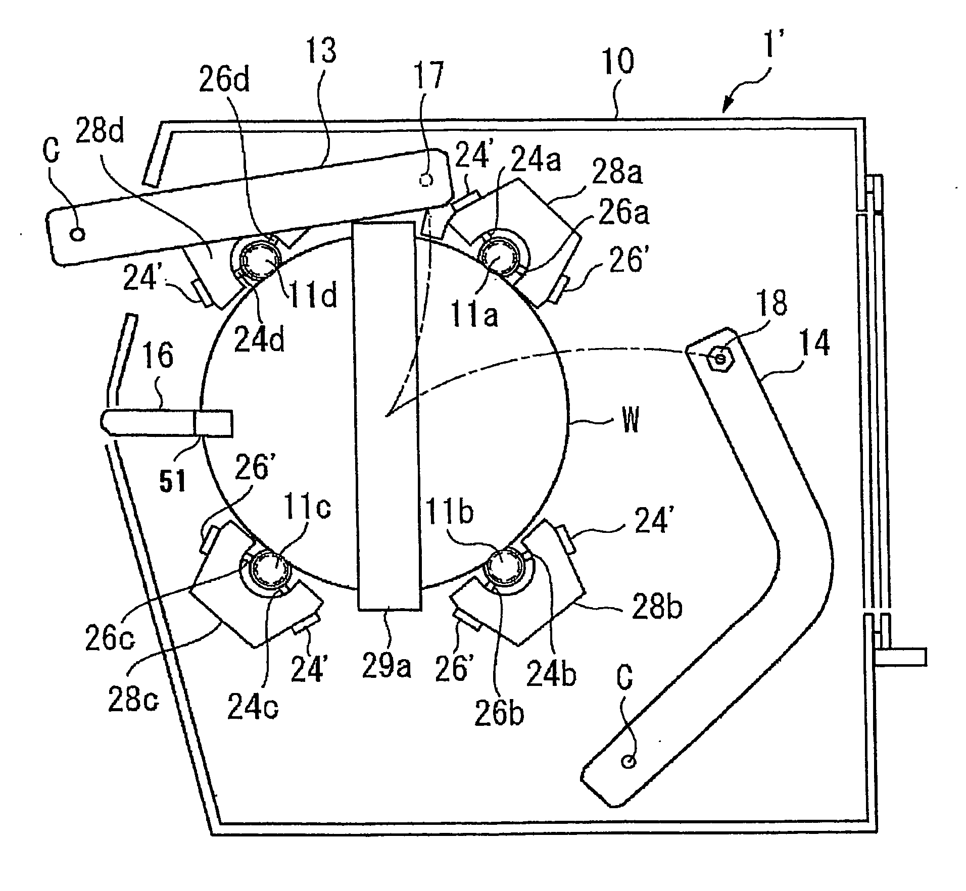
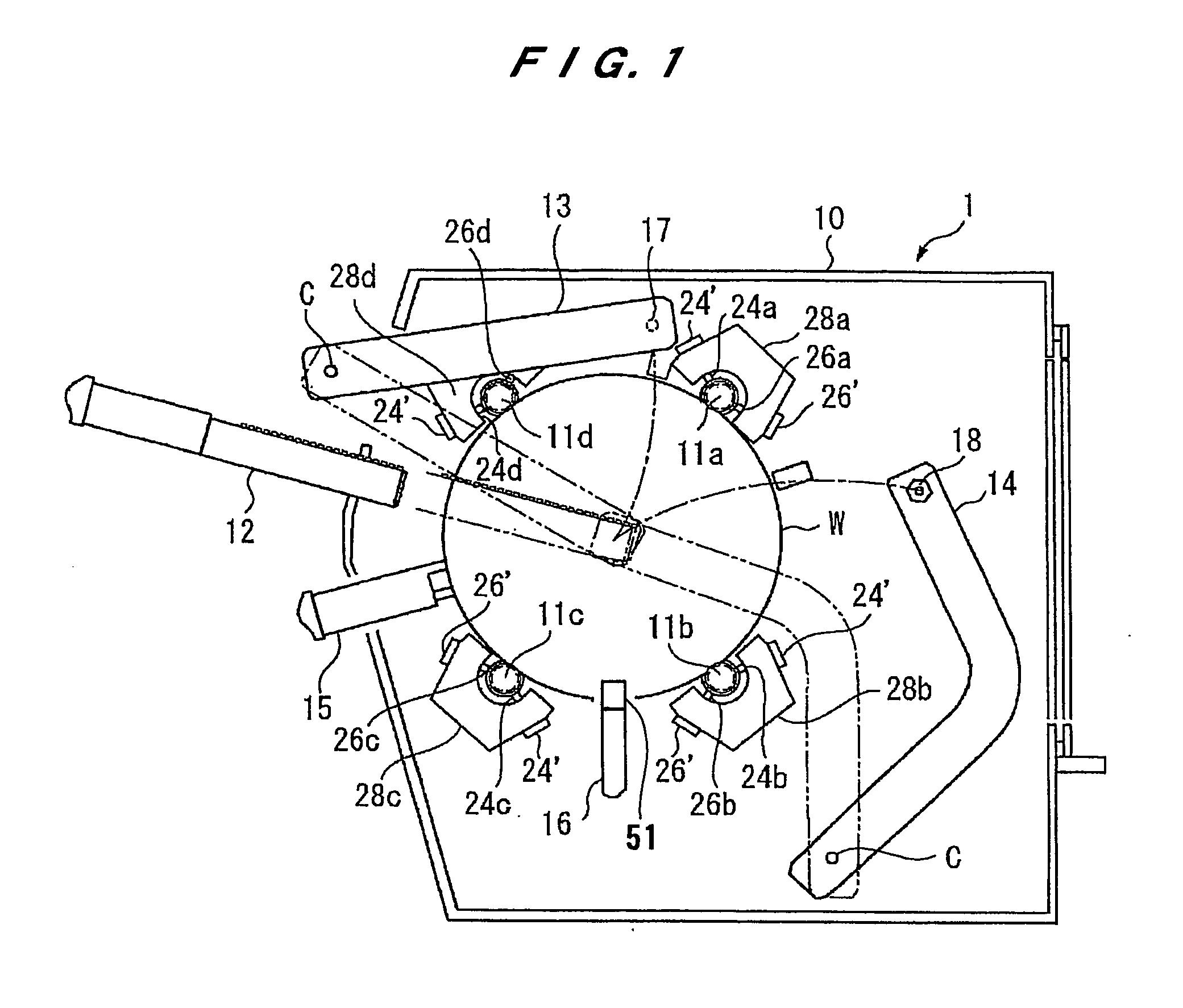
[0148]FIG. 1 is a plan view schematically showing a substrate processing apparatus according to the present invention. This substrate processing apparatus 1 comprises a chamber 10, and substrate holders 11 (11a, 11b, 11c and 11d) disposed in the chamber 10. A substrate W such as a semiconductor wafer is accommodated in the chamber 10, and is held and rotated by the substrate holders 11a, 11b, 11c and 11d. The respective substrate holders 11a, 11b, 11c and 11d have holder suction nozzles (i.e., holder suction units) 24 (24a, 24b, 24c and 24d) and holder cleaning nozzles (i.e., holder cleaning units) 26 (26a, 26b, 26c and 26d), both of which are disposed closely to the substrate holders 11. The holder suction nozzles 24a, 24b, 24c and 24d and the holder cleaning nozzles 26a, 26b, 26c and 26d are supported by support members 28a, 28b, 28c and 28d, respectively. Clearances between the respective holder suction nozzles 24 and the respective substrate holders 11 can be adjusted by adjuste...

third embodiment

[0191] Next, a substrate processing apparatus according to the present invention will be described with reference to FIG. 12.

[0192]FIG. 12 is a schematic perspective view showing a substrate processing apparatus according to a third embodiment of the present invention. Like or corresponding parts of this embodiment are denoted by the same reference numerals as those in the first embodiment, and will not be described below repetitively.

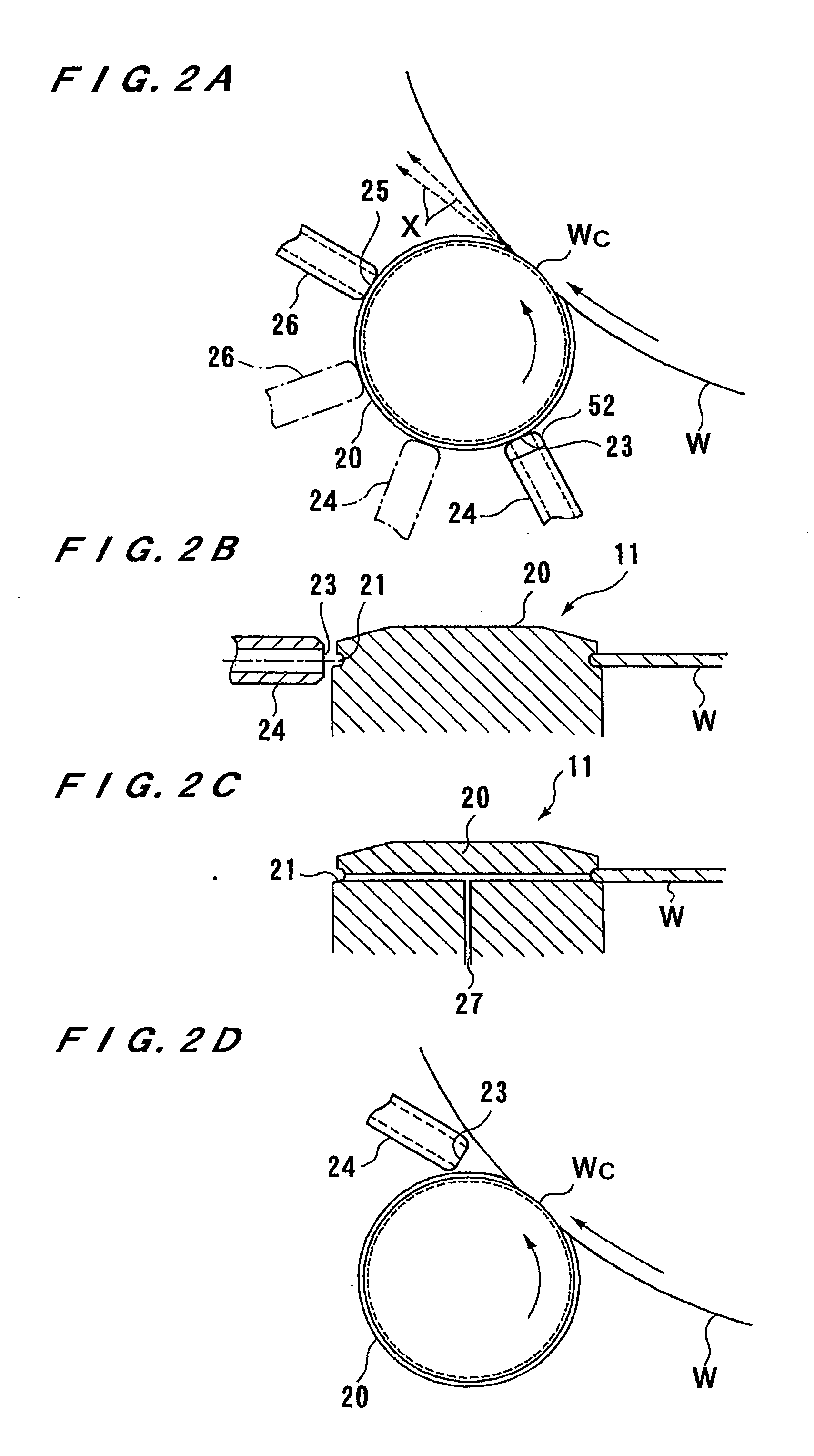
[0193] As shown in FIG. 12, the substrate processing apparatus comprises a plurality of (four in this embodiment) substrate holders 11. The substrate holders 11 comprise rollers 20 which are rotated about their own axes, respectively. Holder suction nozzles 24 for sucking a liquid such as a rinsing liquid which has adhered to clamp portions (see the reference numeral 21 in FIG. 2B) of the rollers 20 are disposed closely to the rollers 20, respectively. These rollers 20 are held in close contact with a peripheral portion of the substrate W and rotated ...

fourth embodiment

[0203] Next, a substrate processing apparatus according to the present invention will be described with reference to FIG. 13.

[0204]FIG. 13 is a schematic perspective view showing a substrate processing apparatus according to the fourth embodiment of the present invention. Like or corresponding parts of this embodiment are denoted by the same reference numerals as those in the third embodiment, and will not be described below repetitively.

[0205] As shown in FIG. 13, a bevel suction nozzle (i.e., a periphery suction unit) 16 is disposed above the substrate W. The bevel suction nozzle 16 is disposed near the peripheral portion of the substrate W so that a liquid on the peripheral portion of the substrate W is sucked by the bevel suction nozzle 16. The bevel suction nozzle 16 has a conductive portion 51 made of an electrically conductive material. This conductive portion 51 is positioned at a tip end of the bevel suction nozzle 16 and is grounded by a wire 47. In this embodiment, altho...


PUM

PropertyMeasurementUnit
thicknessaaaaaaaaaa
thicknessaaaaaaaaaa
thicknessaaaaaaaaaa

Abstract

The present invention relates to a substrate processing apparatus and a substrate processing method for performing a chemical liquid process, a cleaning process, a drying process, or the like while rotating a substrate such as a semiconductor wafer or a liquid crystal substrate. The present invention also relates to a substrate holding apparatus for holding and rotating a substrate. The substrate processing apparatus (1) for processing a substrate (W) while supplying a fluid to the substrate (W) includes a substrate holder (11) for holding and rotating the substrate (W), and a holder suction unit (24) for sucking the fluid from the substrate holder (11). The substrate holding apparatus includes a plurality of rollers (20) which are brought into contact with an edge portion of a substrate (W) so as to hold and rotate the substrate (W), and at least one moving mechanism (303a) for moving the rollers (20).

Description

TECHNICAL FIELD [0001] The present invention relates to a substrate processing apparatus and a substrate processing method for performing a chemical liquid process, a cleaning process, a drying process, or the like while rotating a substrate such as a semiconductor wafer or a liquid crystal substrate. [0002] The present invention also relates to a substrate holding apparatus for holding and rotating a substrate such as a semiconductor wafer, and more particularly to a substrate holding apparatus suitable for use in a cleaning apparatus, an etching apparatus, or the like. BACKGROUND ART [0003] As semiconductor devices have become more highly integrated, there has been a demand for a high yield of the semiconductor devices in a semiconductor fabricating process as well as a demand for a high integration. Particularly, in order to achieve a high yield, a surface of a substrate such as a semiconductor wafer is required to be highly clean, and thus a demand for clarification has been inc...

Claims


Application Information

Patent Timeline
Patent Type & Authority Applications(United States)
IPC IPC(8): H01L21/44B65G47/91B08B1/04B08B3/02C23C18/16C25D7/12H01L21/00H01L21/304H01L21/306
CPCB08B1/04B08B3/02B08B2203/0229B08B2203/0288C25D17/001H01L21/02052H01L21/67028H01L21/67034H01L21/67051C23C18/1628H01L21/02H01L21/304
Inventor YAMADA, KAORUSAITO, TAKAYUKIYABE, SUMIOITO, KENYAKAMEZAWA, MASAYUKISEKI, MASAYAKATAKABE, ICHIROINOUE, YUKI
Owner EBARA CORP
Why Eureka
Try Eureka