Engine transmission mechanism capable of replacing crankshafts and connecting rods and linkage power transmission mechanism

A power transmission mechanism, crankshaft and connecting rod technology, applied in the direction of transmission elements, transmission devices, fluid transmission devices, etc., can solve the problem of increasing the lateral friction between the piston and the cylinder wall, affecting the output power of the engine, and reducing the working efficiency of the piston and other issues to achieve the effect of improving conversion efficiency

Inactive Publication Date: 2015-04-08
安里千
View PDF6 Cites 11 Cited by
  • Summary
  • Abstract
  • Description
  • Claims
  • Application Information

AI Technical Summary

Problems solved by technology

[0005] 2. The swing of the connecting rod in the crankshaft-connecting rod mechanism causes the gas pressure acting on the piston to generate a lateral pressure vertical to the cylinder wall, which increases the lateral friction between the piston and the cylinder wall and accelerates the lateral wear of the cylinder wall. It not only reduces the working efficiency of the piston, but also causes the "cylinder" to make the piston unable to work;
[0006] 3. In the crankshaft and connecting rod mechanism, the unbalanced rotary mass and rotary motion caused by the swing of the connecting rod cause the inertial force, which makes the piston, the cylinder wall and the rotating contact surface produce alternating impact force, which increases the uneven friction and impact between the various components. , not only affects the output power of the engine, but also causes the engine to generate greater vibration and noise

Method used


Image

  • Engine transmission mechanism capable of replacing crankshafts and connecting rods and linkage power transmission mechanism
  • Engine transmission mechanism capable of replacing crankshafts and connecting rods and linkage power transmission mechanism
  • Engine transmission mechanism capable of replacing crankshafts and connecting rods and linkage power transmission mechanism

Examples


Embodiment 1

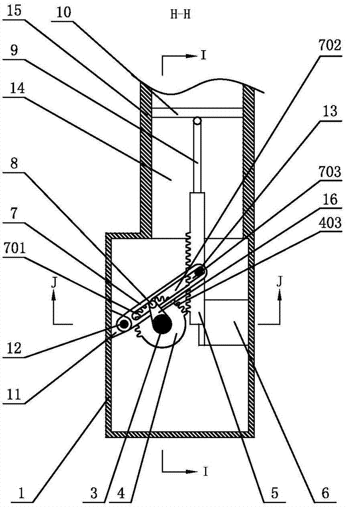
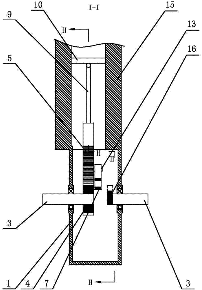
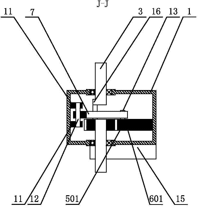
[0040] Such as figure 1 and 2 as shown, figure 1 yes figure 2 The H-H direction sectional view of the engine transmission mechanism that replaces the crankshaft connecting rod in the present embodiment, the engine transmission mechanism that replaces the crankshaft connecting rod includes a housing 1 and a conversion mechanism installed in the housing 1 through two main shafts 3. The conversion mechanism includes a fixed The sector gear 4 at one end of one of the main shafts 3 and the rack 5 installed in the housing 1 through the guide plate 6 and the reset device for driving the rack 5 to reset, the rack 5 alternately meshes with the sector gear 4 and drives the sector gear 4 Rotate, the end of rack 5 is connected with piston 10 through connecting rod 9, and piston 10 is placed in the cylinder 14 of cylinder block 15 to form single-cylinder engine.

[0041] Such as Figure 1-5 As shown, the sector gear 4 is orthogonal to the main shaft 3, the central axis of the sector g...

Embodiment 2

[0052] Such as Figure 10-12 As shown, two sets of power transmission mechanisms with the same structure are arranged in the housing 1, the main shaft 3 connected with the crank arm 16 in the two sets of power transmission mechanisms is coaxially connected, and the side of the sector gear 4 in the two power transmission mechanisms is fixedly connected The main shaft 3 is respectively installed on the two side walls of the housing 1 through the bearing seat and is connected with the external power output mechanism, wherein, when the piston 10 in the engine transmission mechanism of the first set replaces the crankshaft connecting rod and runs to the top dead center of the stroke , the second set of pistons 10 in the engine transmission mechanism replacing the crankshaft and connecting rod just runs to the bottom dead center of the stroke, and the two sets of pistons 10 in the engine transmission mechanism replacing the crankshaft and connecting rod are respectively placed in the...

Embodiment 3

[0055] Such as Figure 13 As shown, in this embodiment, a first power transmission mechanism, a second power transmission mechanism, a third power transmission mechanism and a fourth power transmission mechanism are arranged in the casing 1, and the main shaft 3 installed close to the side wall of the casing 1 passes through the bearing seat respectively. Installed on the two side walls of the housing 1, and respectively connected with the power output mechanism, the adjacent main shaft 3 in the housing 1 is coaxially connected, the first power transmission mechanism and the rotating arm 7 of the third power transmission mechanism, The rack 5, the connecting rod 9 and the piston 10 move in the same direction, the rotating arm 7, the rack 5, the connecting rod 9 and the piston 10 move in the same direction as the second power transmission mechanism and the fourth power transmission mechanism, and the first power transmission mechanism and the piston 10 move in the same direction...


PUM


Abstract

The invention discloses an engine transmission mechanism capable of replacing crankshafts and connecting rods. The engine transmission mechanism comprises sector gears, racks and rotary arms. Each sector gear is mounted at an end of a spindle, the racks can slide on guide plates and can be reset by the aid of the rotary arms, the racks and the gear sectors are alternately meshed with one another, the spindles can rotate along with the driving sector gears and output power, journals on the side surfaces of the sector gears and resetting round bars on the side surfaces of the racks alternately drive the rotary arms by the aid of journal slide grooves and reset slide grooves to swing in a reciprocating manner, the journal slide grooves and the reset slide grooves are formed in the rotary arms, end teeth at one end of each sector gear are separated from end teeth at one end of the corresponding rack when pistons are positioned at lower dead centers, collision of the journals and ports of the journal slide grooves can be prevented by the journals by the aid of guide grooves of the rotary arms, collision of end teeth at the other end of each sector gear and end teeth at the other end of the corresponding rack can be prevented by the journals by the aid of the guide grooves when the pistons cross upper dead centers, and accordingly reciprocating linear movement of the pistons and rotation movement of the sector gears can be stably switched over. The engine transmission mechanism has the advantages that the engine transmission mechanism can replace crankshaft and connecting rod transmission actuators, accordingly, inherent shortcomings of crankshaft and connecting rod mechanisms can be overcome, and the conversion efficiency of engines can be greatly improved.

Description

technical field [0001] The invention relates to an engine transmission device, in particular to a reciprocating linear motion and circular motion conversion mechanism to replace the engine transmission device of the crankshaft connecting rod mechanism. Background technique [0002] In mechanical engineering, such as piston engines, compressors and other machines that need to convert linear reciprocating motion and circular motion, crankshaft (crank) connecting rod conversion mechanism is generally used at present. [0003] The design and manufacture of the traditional crankshaft-connecting-rod mechanism have been very perfect, but there are inherent defects in both theoretical analysis and practical application: [0004] 1. The conversion efficiency of the crankshaft connecting rod mechanism is low. Taking the piston-connecting rod-crankshaft conversion mechanism engine as an example, the gas pressure acting on the piston is transmitted to the crankshaft through the connect...

Claims


Application Information

Patent Timeline
Patent Type & Authority Applications(China)
IPC IPC(8): F16H19/02F16H19/04
CPCF16H47/02F16H2702/00
Inventor 安里千刘庆毛灵涛刘升贵
Owner 安里千
Why Eureka
Try Eureka