Rotor for a rotary electric machine and rotary electric machine

Pending Publication Date: 2022-10-27
WEG EQUIP ELETRICOS SA
View PDF0 Cites 0 Cited by
  • Summary
  • Abstract
  • Description
  • Claims
  • Application Information

AI Technical Summary

Problems solved by technology

As a consequence, there is still the generation of additional losses by ventilation as a resul

Method used


Image

  • Rotor for a rotary electric machine and rotary electric machine
  • Rotor for a rotary electric machine and rotary electric machine
  • Rotor for a rotary electric machine and rotary electric machine

Examples


first embodiment

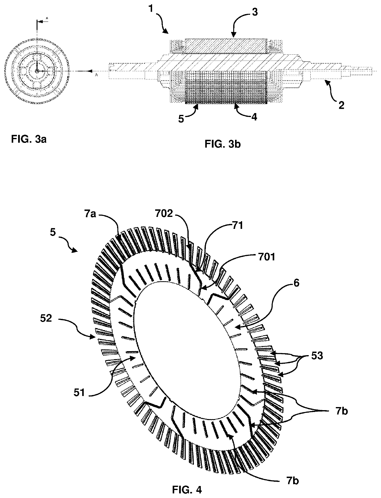
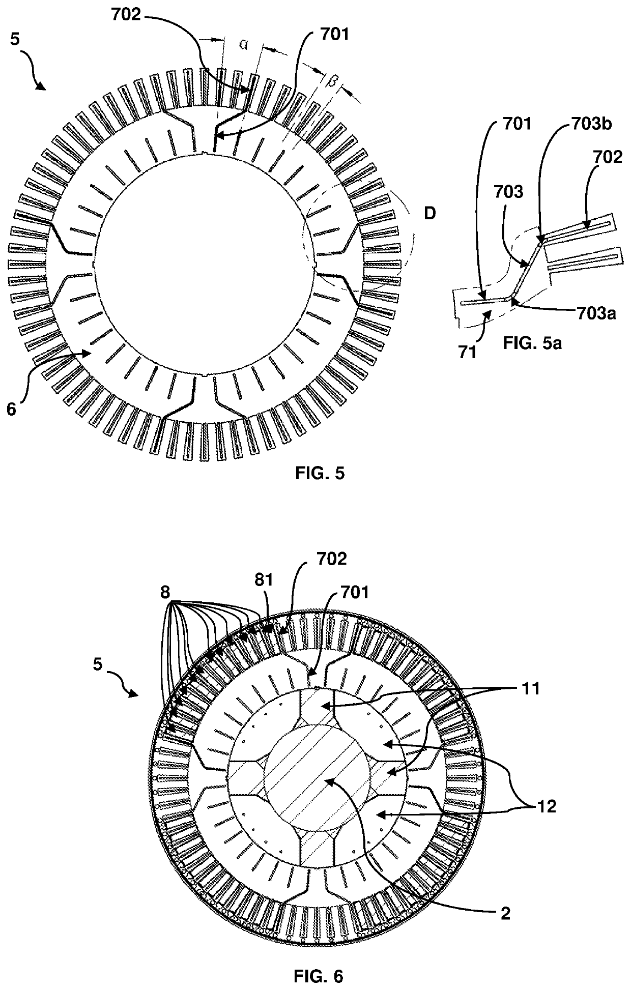
[0048]FIGS. 4 to 6 show the spacer plate (5) according to the present invention.

[0049]As can be seen in this figure, the spacer plate (5) comprises a base plate (6) which comprises a plurality of spacer profiles (7). This base plate (6) may have a simplified geometry when compared to the main plate (4), that is, the cutting geometry of the base plate (6) does not need to be identical to the main plate (4).

[0050]In the same way as in the main plates, although possibly in a simplified geometry, the spacer plate (5) comprises a crown region (51) close to the shaft and a peripheral region (52) with slots (53).

[0051]The spacer profiles (7) may have an arrangement distinct from that presented in the illustrated embodiments of the present invention, and may vary in quantity depending on the variation of the number of slots of the rotor. Furthermore, variation is allowed in both the size and arrangement of the spacer profiles (7) in both the direct axis and the quadrature axis, in the crown...

second embodiment

[0064]Alternatively, in the embodiment shown in FIG. 7, the guiding spacer profile (710) is formed of individual profile portions (711, 712, 713) joined by welding or a similar process. Thus, in this second embodiment of the present invention, there are no profile fold regions. In this configuration, it is necessary that the positioning of the individual profile portions (711, 712, 713) is such that it results in the shortest possible distance d between them.

third embodiment

[0065]FIG. 8 shows the spacer plate according to the present invention, wherein the at least one guiding spacer profile (720) comprises only a first end portion (721) and a second end portion (722).

[0066]Thus, in this embodiment, the first end portion (721) extends, in a straight path, from the crown region (501) of the spacer plate (50) to the second end portion (722) arranged in the peripheral region (502) of the spacer plate (50).

[0067]Preferably, the first end (721) of the guiding profile (720) should be at about 10 mm from the inner edge of the base plate (60), while the second end (721) of the spacer profile (720) should be at an optimal distance of about 5 mm from the outer edge of the base plate (60). The length of the segment formed by the first extended end (721) must correspond to half the total dimension of the crown of the plate (60), and the length of the second end (722) must have a dimension equivalent to the height of the slot (530).

[0068]It is noteworthy that in th...


PUM


Abstract

A rotor for a rotary electric machine is provided, the rotor including a pack of plates mounted on a shaft, the pack having a plurality of main plates mounted alternately with another plurality of spacer plates and the spacer plates having a base plate with a plurality of spacer profiles, the spacer plate having a crown region close to the shaft and a peripheral region with slots, wherein the plurality of spacer profiles includes at least one guiding spacer profile that has a first end portion arranged radially in relation to the shaft in the crown region of the spacer plate and a second end portion arranged radially in relation to the shaft in the peripheral region of the spacer plate, and the second end portion is offset angularly in relation to the first end portion.

Description

FIELD OF THE INVENTION[0001]The present invention relates to the field of rotary electric machines having a ventilation circuit in which the flow of cooling air flows radially through the pack of plates of the rotor towards the stator.BACKGROUND OF THE INVENTION[0002]Electric machines are equipment used for the transformation of electrical energy into mechanical energy, in the case of motors, and vice versa, in the case of generators. They are constituted by four basic structures, namely: the rotor, which is the rotary energized component, a static element called a stator, also energized, bearings responsible for joining the static and rotary parts, and finally the casing that constitutes not only the role of enclosure of the systems already mentioned, but promotes integration with other auxiliary systems. Auxiliary systems are considered to be those of excitation, cooling, lubrication, among others that can coexist with the main ones, depending on the construction and technical req...

Claims


Application Information

Patent Timeline
IPC IPC(8): H02K1/32
CPCH02K1/32H02K2213/03
Inventor SCHNEIDER POREPP, GUILHERMEVOLTOLINI, DANIELLE RAPHAELA
Owner WEG EQUIP ELETRICOS SA
Why Eureka
Try Eureka